180
SYNRAD FH Series Flyer Operator’s Manual Version 3.4
maintenance/
troubleshooting
Maintenance
T
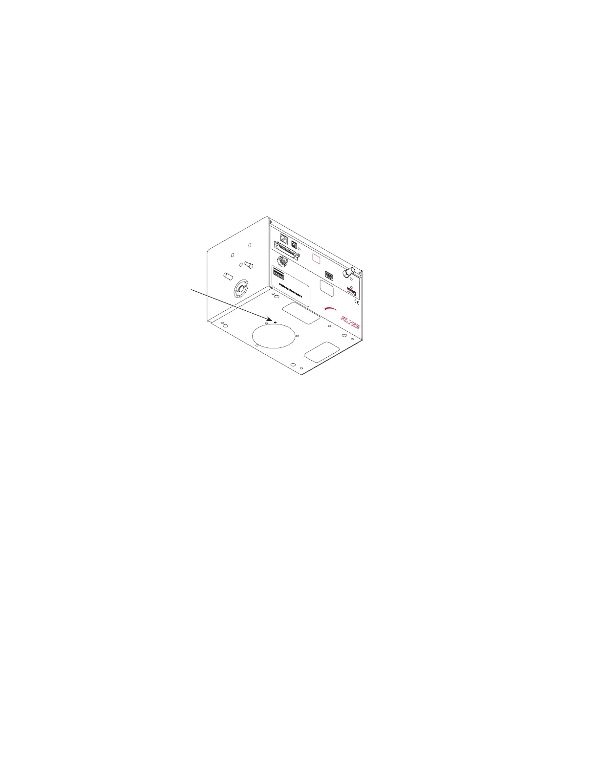
o replace the FH Flyer focusing lens, perform the following steps:
1
If the focusing lens assembly has a dowel pin on its inside face, refer to Figure 7-2 and position
the
lens mount so that the dowel pin lines up with the non-threaded dowel pin hole in Flyer’s bottom
plate.
Figure 7-2
Lens mount dowel pin location
2
Insert the dowel pin into the dowel pin hole, then rotate the lens slightly as required so the screw
holes align with the threaded holes in Flyer’s bottom plate.
If the lens mount does not have a dowel pin, simply line up the screw holes in the lens mount with
the threaded holes in Flyer’s bottom plate.
3
Hold the lens in position, then insert and loosely fasten the three 8–32 × 3/8" Allen cap screws.
4
While carefully tightening the three cap screws, inspect the lens mount assembly around its circum-
ference and verify that the lens mount ts ush against the bottom plate.
Note: If the lens mount assembly does not t ush against the bottom plate, remove the lens and re-
check the alignment and t of the dowel pin.
ETHERNET
USB
LASER
CONTROL
POWER
USER INTERFACE
TEST
MARK
STATUS
PWR
FH
MARKING HEAD
FLYER
GAS PURGE
CLEAN AND DRY AIR
OR NITROGEN ONLY
2-5 PSI
AVOID EXPOSURE
Invisible laser radiation
is emitted from
this aperture.
OEM Product
Does not comply with 21 CFR
Subchapter J or EN60825
without additional safeguards.
DO NOT
CONNECT OR
REMOVE CABLE
WHILE DC POWER
IS ENERGIZED
4600 Campus Place, Mukilteo, WA 98275 (425) 349-3500
MODEL#: FHFL30-U
TESTED AT: 30 VOLTS
MFG: August 31, 2009
Ser#: FHFL033070003