Chapter 5 Wiring
Wiring consideration
5-11
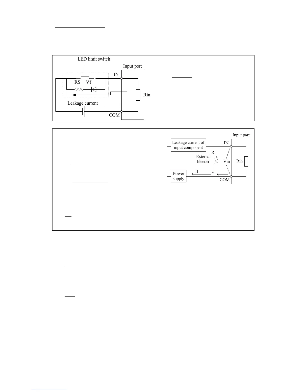
4.2.2 Leakage current of Input component
AS for the following example, when there is leakage current as signal OFF, and larger than the
module OFF current, the module can not OFF or Onise margin will not work as module is OFF.
<Reference >
Formulation for leakage current
RsRin
VfV
iL
+
=
V: Power voltage
Vf: voltage drop on LED.
Rs: resistance of current limit
Rin: internal impedance of input module
Refer to the circuit diagram of the solution
eliminating the effect of leakage current, the
resistance of R should comply with the following
formulation.
VinOFF
RRin
RRin
iL <
+
×
× )(Q
toleranceA
VinoffiLRin
RinVinOFF
R ×
⎟
⎟
⎠
⎞
⎜
⎜
⎝
⎛
−×
×
<
Tolerance A: 0.7
Power for bleeder resistor:
toleranceB
R
V
W ×>
2
Tolerance B: 1.5
iL: leakage current
Vin OFF: Off level for input signal
Rin: Internal resistor of input
V: Power voltage
For example: basic unit TP03-30MR, pow
,
er supply voltage=24V VinOFF=15V, Rin=3.5kΩ.
。
given leakage current for input component = 6.5mA
That is iL=6.5mA, Vin OFF=15V, Rin=3.5kΩ, V=24V
Ω75.47.0
155.65.3
5.315
kR =×
−×
×
<
R=4.75kΩ , if standard resistor R=4.7 kΩ. then
W
k
W 18.05.1
7.4
24
2
=×>
A resistor 4.7kΩ with power 1/4W should be applied as the bleeder resistor.