Chapter 3 Expansion unit specification
expansion unit 3-14
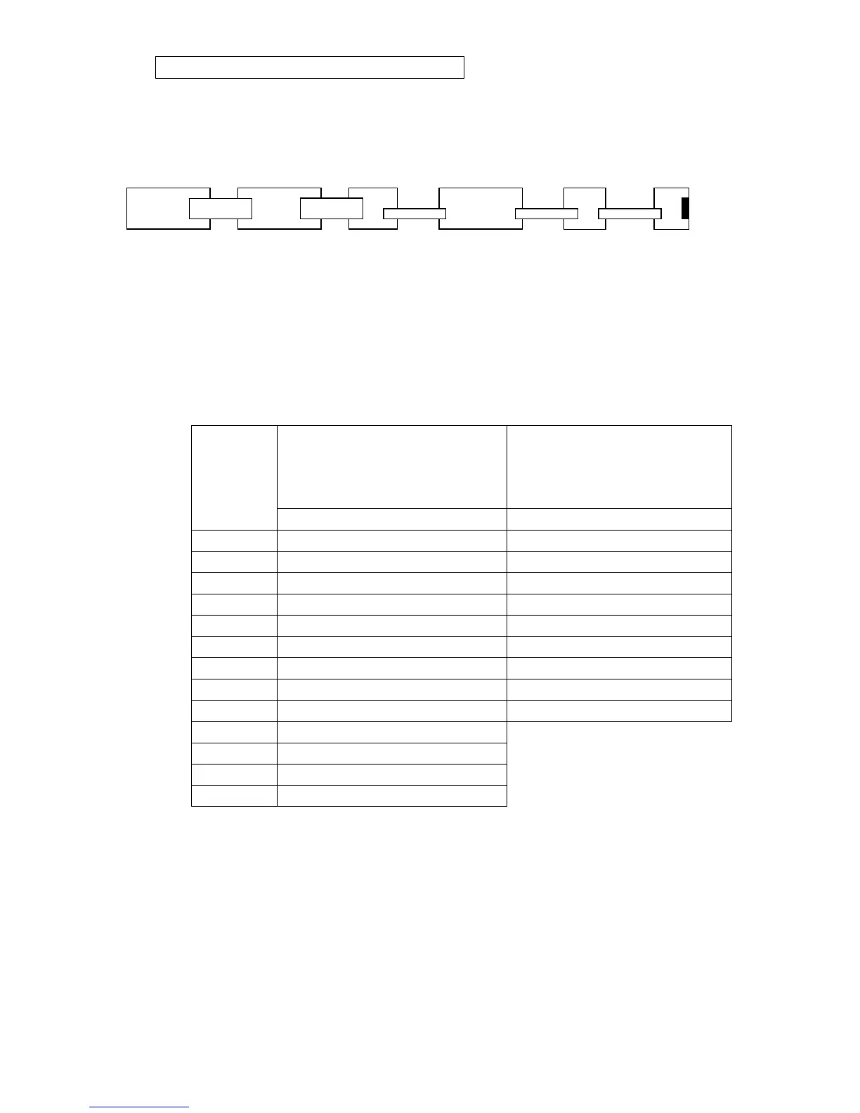
Example 2: Max basic system configuration
Max configuration includes several common I/O expansion units (max 256 points) +
(TP02-4AD)*1+(TP03-8AD)*7+(TP02-2DA)*1+(TP03-2DA)*4
Note:
1. Among all the expansion units for TP03 basic unit, the TP02 expansion should be installed
after TP03 expansion unit, including I/O module, AD and DA module.
2. Then the last unit should be plugged with terminal connector (TP-200EC).
3. the figure is only the logic connect. In fact some of power module will be added into due to
different application.(refer to 3.)
2.1.2 Data register and channel of analog expansion module
System will read data in the channel and write them in the data address.
Analog expansion module for input
(System will the read data from
individual channels to corresponding
address)
Analog expansion module for output
(System will the read data from
corresponding address to individual
channels)
Channel
Data address Data address
Channel 1 D8436 D8381
Channel 2 D8437 D8382
Channel 3 D8438 D8383
…… …… ……
Channel 1 D8444 D8389
Channel 2 D8445 D8390
…… ……
Channel 59 D8494
Channel 60 D8495
Channel 61 D8496 (Reserved)
Channel 62 D8497 (Reserved)
Channel 63 D8498 (Reserved)
Channel 64 D8499 (Reserved)
Basic unit(60HR)(TP03-8AD)*7 (TP03-2DA)*4 (TP02-32EMR)*6 (TP02-4AD+) (TP02-2DA+)