Chapter 5 Wiring
Basic unit wiring
5-5
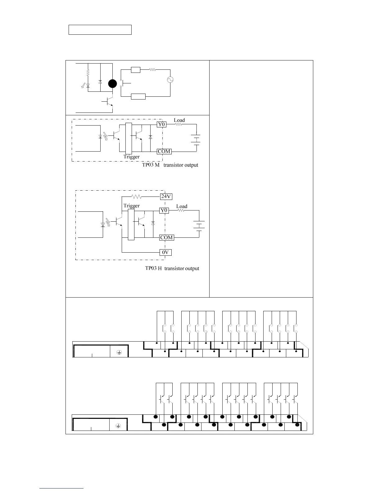
2.3 Output wiring
RY
Y0
COM
AC
LED
Load
Relay output
1. PLC Output has two types: relay and
transistor. Please refer to chapter 2 for
electric specification related to it.
2. Operation indicator: When the output
is ON, the corresponding indicator will
be lit.
3. Insulation circuit:
For transistor output:
PLC internal circuit is photo-coupling
insulated.
For relay output:
PLC internal circuit is relay insulated.
4. Please pay attention to common
terminal’s wiring for output. Take
TP03-30MT-A as an example, Y0~Y1
share COM0, Y2~Y5 share COM1,
Y6~Y11 share COM2 and Y12~Y15
share COM3. See the following figure
for transistor output type.
For relay output:
7
100~240VAC
LN
3
COM1
0
5
6
COM0
1
2
COM2
4
13
COM3
10
15
11 12
14
For transistor output:
COM1
100~240VAC
LN
0
COM0
1 11
35
610
COM2
2 4 7
COM3
13
15
14
12