Chapter 5 Wiring
Basic unit wiring
5-6
Over load capacity for output terminal
Each output terminal has the overload capacity of 2 times of rated current/ 5Min and the common
terminal has 1.5 times of rated current/ 2Min. If that exceeds limited range, the terminals will be
fault or even the internal circuit will be dangerously burned.
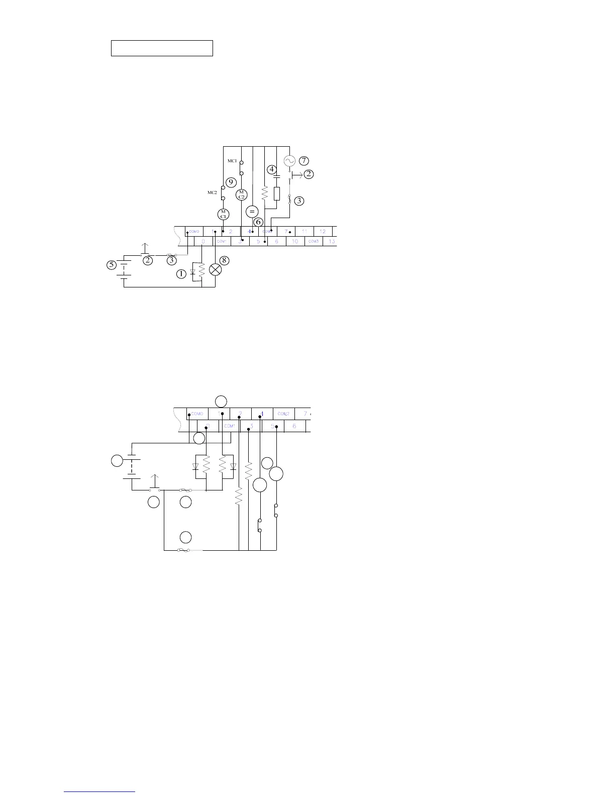
Wiring example for Relay output type
①Diode for absorbing surge: to extend
the terminals lifespan.
②Emergency stop: use external switch
③Fuse: connect the fuse at output
common terminal with the capacity of
5~10A in order to protect output circuit.
④Surge absorber: to reduce the noise
from AC load
⑤DC power supply
⑥Indicator: neon lamp.
⑦AC power supply
⑧Incandescent lamp (resistance load)
⑨Mutually locked Output: to connect an external mutually locked circuit matching with PLC
internal program to provide safety protection for any exceptional condition.
◎Wiring example for Transistor output type
①DC power supply
②Emergency stop
③Fuse for protecting circuit
④All outputs for transistor type are Open
Collector. If Y0 is set to pulse output (PLSY
instruction), please connect a resistor to
maintain the output current >0.1A in order to
ensure output normal operating.
⑤All outputs for transistor type are Open
Collector. If Y1 is set to pulse output (PWM
instruction), please connect a resistor to
maintain the output current >0.1A in order to ensure output normal operating.
⑥Mutually locked Output: to connect an external mutually locked circuit matching with PLC
internal program to provide safety protection for any exceptional condition.
1
2 3
3
4
5
6
MC1
MC2
MC2
MC1


 To Next Page