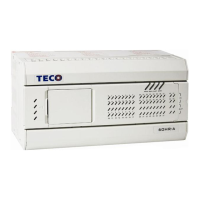
I
Contents
Chapter 1 TP03 Introduction......................................................................................................... 1-1
1 Model type description....................................................................................................... 1-2
2 Product type ....................................................................................................................... 1-3
2.1 Basic module list..................................................................................................... 1-3
2.2 Expansion module list............................................................................................. 1-6
2.3 Programming tool.................................................................................................... 1-8
2.4 Accessory list.......................................................................................................... 1-9
3 System configuration ....................................................................................................... 1-10
4 OP07/08-TP03 cable (TP03-302MC) specification..........................................................1-11
5 TP03-302PC cable specification...................................................................................... 1-12
6 TP03 PC/PDA port connect with HMI by RS-422........................................................... 1-13
6 TP03 terminal block......................................................................................................... 1-13
Chapter 2 Basic Unit Specification............................................................................................. 2-1
1 Function ............................................................................................................................. 2-1
1.1 General specification............................................................................................... 2-1
1.2 AC type Power supply specification ....................................................................... 2-3
1.3 DC type Power supply specification....................................................................... 2-3
1.4 General features for basic unit ................................................................................ 2-4
1.5 Environment specification....................................................................................... 2-5
2 Digital input/output............................................................................................................ 2-6
2.1 Digital input ............................................................................................................ 2-6
2.2 Digital output point ................................................................................................. 2-6
3 Communication ports......................................................................................................... 2-8
3.1 Communication ports position................................................................................ 2-8
3.2 Function description for 3 communication port...................................................... 2-9
3.3 Three communication ports description.................................................................2-11
3.3.1 Modbus slave communication.....................................................................2-11
3.3.2 Data link..................................................................................................... 2-21
3.3.3 REMOTE I/O instruction........................................................................... 2-21
3.3.4 RS/MBUS instruction ................................................................................ 2-22
3.4 Wiring methods..................................................................................................... 2-22
4 High speed counter........................................................................................................... 2-24
4.1 General characteristic of high speed counter ........................................................ 2-24
4.2 Number for Built-in high speed counter................................................................ 2-24
4.3 Function ................................................................................................................ 2-26
4.4 Application example for 1 phase high speed counter............................................ 2-27
4.4.1 1 Phase 1 input ........................................................................................... 2-27
4.4.2 1 Phase 2 input ........................................................................................... 2-28
4.5 Application example for 2 phase high speed counter............................................ 2-28
4.5.1 2 Phase 2 inputs.......................................................................................... 2-28
4.5.2 Action of 2 phase input signal.................................................................... 2-29
4.6 Output counting result........................................................................................... 2-29
4.7 Restrictions for fastest responding frequency....................................................... 2-29
4.8 Common consideration: ........................................................................................ 2-30
5 Interruption Input............................................................................................................. 2-31
6 Pulse output...................................................................................................................... 2-32
7 Expansion card................................................................................................................. 2-32
8 Built-in memory and memory card (TP03-1ME)............................................................. 2-33
9 Password .......................................................................................................................... 2-34
10 RUN/STOP switch......................................................................................................... 2-34
11 RTC ................................................................................................................................ 2-35
12 Potentiometer................................................................................................................. 2-36
13 Battery............................................................................................................................ 2-37
13 Instruction ...................................................................................................................... 2-37

 Loading...