EasyManua.ls Logo

TECO TP03 PLC User Manual

TECO TP03 PLC
152 pages
To Next Page IconTo Next Page
To Previous Page IconTo Previous Page
Page #51 background imageLoading...
Page #51 background image
Chapter 2 Basic Unit Specification
4. High speed input
2-29
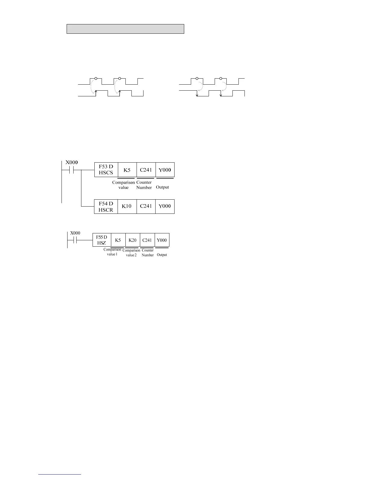
4.5.2 Action of 2 phase input signal
z 2 phase encoder can produce A phase and B phase with 90° phase difference to A phase. Such
high speed counter can automatically up count or down count.
z The following indicates operation of 2 phase counter.
A phase
B phase
+1 +1 -1 -1
Time
Forward: up counting Reverser: down counting
A phase
B phase
Time
4.6 Output counting result
The output should be enabled immediately as long as the present value reaches the set value of
high speed counter, so the special application instructions should be used.
A. <<Comparison set/reset instruction for high speed counter>>
z When reaching the comparison value, the
interruption will be on (Y000 ON).
z Please select transistor output type. As for
relay output type, the PLC has a mechanical
delay about 10ms.
B. <<Zone comparison instruction for high speed counter>>
z Zone comparison instruction of high-speed
K10C241 present value Y000 ON
K10C241 present valueK20 Y001 ON
C241 present valueK20 Y002 ON
Regarding to general application instruction F10 (CMP) and FNC11 (ZCP), there will be a delay
because of PLC scan time. In order to avoid that delay in high speed counting, the above
instructions F53, F54 and F55 have nothing to do with scan time and the output will operate
immediately.
4.7 Restrictions for fastest responding frequency
Regarding to hardware, the input X000~X005 has the competence to accept 100 kHz signal.
However, with respect to software, please take the following items into consideration:
A. When C235
C238,C241,C242,C244,C245 are set as up-counting counter, its max
frequency could be 100KHz.
B. When C235
C238,C241,C242,C244,C245 are set as up/down counting counters or as
down-counting ones, its max frequency could be 5KHz.
C. The C239
C240,C243,C246~C249 counters could accept the max frequency, 5KHz
D. The C251
C254 counters could accept the max frequency 100KHz.
E. When the system is preoccupied by a lot of other functions (such as frequent
communication/ longer program/longer scan time/ many interruptions/ pulse output/
compare instruction for high speed counter), it is suggest that the max average frequency
of high speed counter should be decreased properly.

Table of Contents

Question and Answer IconNeed help?

Do you have a question about the TECO TP03 PLC and is the answer not in the manual?

TECO TP03 PLC Specifications

General IconGeneral
BrandTECO
ModelTP03 PLC
CategoryController
LanguageEnglish

Summary

Chapter 1 TP03 Introduction

1 Model type description

Explains how to interpret the model numbers for basic and expansion units.

2 Product type

Lists and categorizes various basic, expansion, communication modules, and programming tools.

3 System configuration

Illustrates how basic and expansion units connect to form a system.

4 OP07/08-TP03 cable (TP03-302MC) specification

Details the pin definition and internal connection of the OP07/08-TP03 cable.

5 TP03-302PC cable specification

Details the pin definition and internal connection of the TP03-302PC cable.

6 TP03 PC/PDA port connect with HMI by RS-422

Explains the PC/PDA port connection to HMI using RS-422, including pin assignments.

7 TP03 terminal block

Shows the terminal block layout for various TP03 basic units.

Chapter 2 Basic Unit Specification

1 Function

Details the core functions, general specifications, power supply, features, and environmental requirements of the basic TP03 unit.

2 Digital input/output

Describes the electrical specifications and wiring for digital inputs and outputs.

3 Communication ports

Details the location, function, and settings for the three communication ports.

4 High speed counter

Explains characteristics, number of counters, functions, and application examples.

5 Interruption Input

Details how to configure inputs for interruption and the associated pointer assignments.

6 Pulse output

Specifies pulse output capabilities, PWM output, frequency, and application instructions.

7 Expansion card

Explains the availability and installation of expansion cards for the basic unit.

8 Built-in memory and memory card (TP03-1ME)

Describes the types of memory, saving content, and saving places for built-in and external memory.

9 Password

Explains how to set passwords for program protection and their different levels.

10 RUN/STOP switch

Details the three modes for controlling the PLC's RUN/STOP state.

11 RTC

Covers the Real-Time Clock specifications, special application instructions, and setting the time.

12 Potentiometer

Explains the built-in analog potentiometers and their use for setting values.

13 Battery

Provides specifications for the battery, its usage, and handling precautions.

14 Instruction

Refers to Chapter 7 for instruction set details.

Chapter 3 Expansion unit specification

1 Digital expansion unit

Covers general specifications, outline dimensions, and electrical specifications for digital expansion units.

2 Analogue expansion unit

Introduces analog expansion units, their system configuration, and data registers.

3 How many expansion unit can be connected to base unit

Explains limitations on connecting expansion units based on base unit type and power consumption.

Chapter4 Dimension and installation

1 Outline dimension

Provides dimensional drawings for the basic TP03 units.

2 Installation

Guides the user through the installation process, including ambient environment and mounting methods.

Chapter 5 Wiring

1 Wiring

Provides general guidelines for wiring, including torsion torque and wire routing.

2 Basic unit wiring

Details power supply wiring for AC and DC types, including terminal connections and precautions.

3 Expansion unit wiring

Shows input and output wiring diagrams for various expansion units.

4 Wiring consideration

Provides guidelines for input power, input signals, and output terminals to ensure correct operation.

5 Solving noise problem

Offers solutions for noise reduction, including grounding, power source noise, and thunder stroke protection.

Chapter 6 Trial Run

1 Trial run

Outlines checks to perform before powering on the PLC and its wiring.

2 Maintenance and Inspection

Details periodic inspection items for basic units and expansion units to ensure optimal operation.

3 Troubleshooting

Guides users through diagnosing and resolving errors based on LED indicators and specific procedures.

Chapter 7 Instruction List

1 Basic sequential instruction

Explains fundamental logical operations like Load, AND, OR, and their variations.

2 Step instruction :STL, RET

Describes the Step Ladder ([STL]) and Step Ladder Return ([RET]) instructions.

3 Application instruction list

Lists various application instructions categorized by function.

Chapter 8 Special Relay

PC status (M)

Details special relays related to PC status, including RUN monitor and error flags.

Clock device(M)

Lists special relays for clock functions like period oscillators and time setting.

Operation flags(M)

Describes operation flags related to zero, borrow, carry, and program execution.

PC status(D)

Lists special data registers for PC status, version, and error codes.

RTC(D)

Details special data registers for Real-Time Clock functions like scan times and date/time components.

PC operation mode(M)

Covers special relays for controlling PC operation modes and register clear functions.

PC mode(D)

Specifies data registers for constant scan mode settings.

Step ladder flags (M)

Lists special relays for controlling Step Ladder execution and annunciator functions.

Step ladder flags (D)

Details data registers used for Step Ladder ON state addressing.

Interruption disable(M)

Describes special relays for enabling or disabling input and timing interruptions.

UP/DOWN counting set device(M)

Lists special relays used to set the UP/DOWN counting modes for counters.

Devices(M)

Lists special relays related to expansion card errors, hardware checks, and communication errors.

Error detection(D)

Lists special data registers for error codes related to various functions.

Communication and link (M) I

Details special relays for RS485 communication port status and MBUS instructions.

Communication and link (D) I

Specifies data registers for RS485 and expansion communication port settings.

Communication and link (M) II

Lists special relays related to RMIO communication and expansion port status.

Communication and link (D) II

Specifies data registers for DTLK communication parameters.

High speed and position (M)

Covers special relays for high-speed counter zone compare, speed detection, and pulse output status.

PWM output(D)

Details data registers for PWM time base settings.

Expansion (M)

Lists special relays for processing modes like SWAP and HEX data processing.

High speed and position(D)

Specifies data registers related to high-speed counter zone compare and pulse output values.

OP07/08(M)

Lists special relays corresponding to OP07/08 keypad functions (F1-F12, Up/Down, Left/Right, TMR, CNT, ENT, MOD, ESC).

OP07/08(D)

Details data registers for OP07/08 display content, mode settings, and data formats.

AD/DA (M)

Lists special relays for setting AD/DA module modes and error detection.

AD/DA (D)

Specifies data registers for setting AD/DA channel modes and for reading/writing AD/DA data.

Related product manuals