Chapter 2 Basic Unit Specification
4. High speed input
2-27
4.4 Application example for 1 phase high speed counter
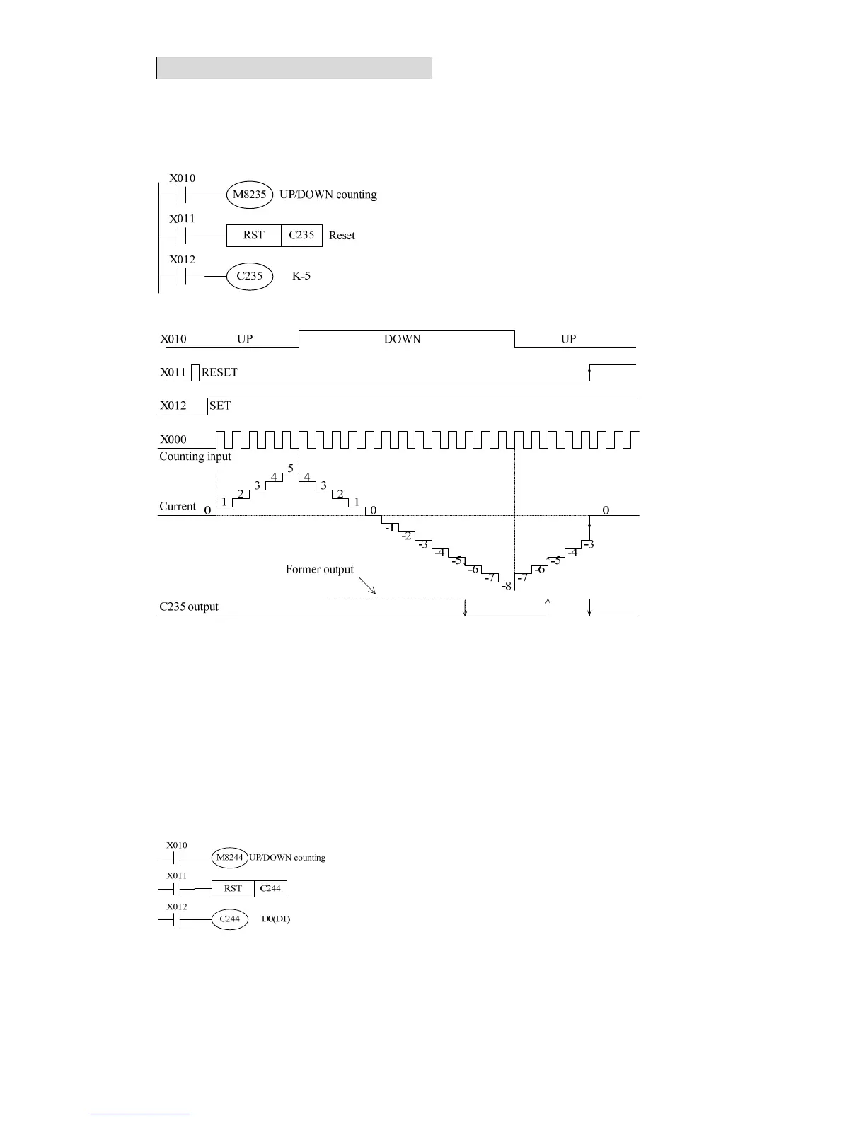
4.4.1 1 Phase 1 input
X010 OFF: up counting; X010 OFF: Down
counting
If X011 is enabled, C235 will be reset (RST).
When X012 is ON, C235 will count input X000.
z X010 controls C235 up/down counting.
z When the present value changes from -6 to -5, the output of C235 will be ON. While as the
present value changes from -5 to -6, the output of C235 will be OFF.
z The output action has not relation to present value. The value 2,147,483,647 will change to
-2,147,483,648 as up counting is operated, also, the value -2,147,483,648will change to
2,147,483,647 as down counting is operated.
z When X011 is enabled, the instruction RST will be operated, namely, the current value will
be cleared to 0 and output will be OFF.
z As for the retentive high speed counter, the present value and output state (ON/OFF) will be
kept as power fails.
When X012 is ON, and input X004 is also ON, C244
starts to count X000 pulse. In the example, the set value
can be data in index register (D1, D0).
When X001 is ON, C244 will be set at once. However,
such reset action also can be accomplished by sequential instruction RST, as above figure.
M8235~M8245 ON / OFF can control C235~C245 counting direction.