Chapter 3 Expansion unit specification
expansion unit 3-25
2.5.6 TP03-2DA Specification
Specification
Item
Voltage Current
V0-C0,V1-C1: 0V~10V or 1V~5V
±V0-C2, C1-C3: -10V~ +10V.
I0-C0,
I1-C1:
0mA~20mA or
4mA~20mA.
Analog output range
external impendence should be more than
500Ω
external impendence should be
less than 500Ω.
Data range
0000(0V) ~ 4000(10V) or
0000(1V) ~ 2000(5V) or
0000(-10V)~4000(+10V)
0000(0mA) ~ 2000(20mA) or
0000(4mA) ~ 2000(20mA)
Resolution 2.5 mV 10 μA
Accuracy ±1% or less (at 25 )℃ ±1% or less (0~55 )℃
Transmit speed 1scan time/ 4 Channel
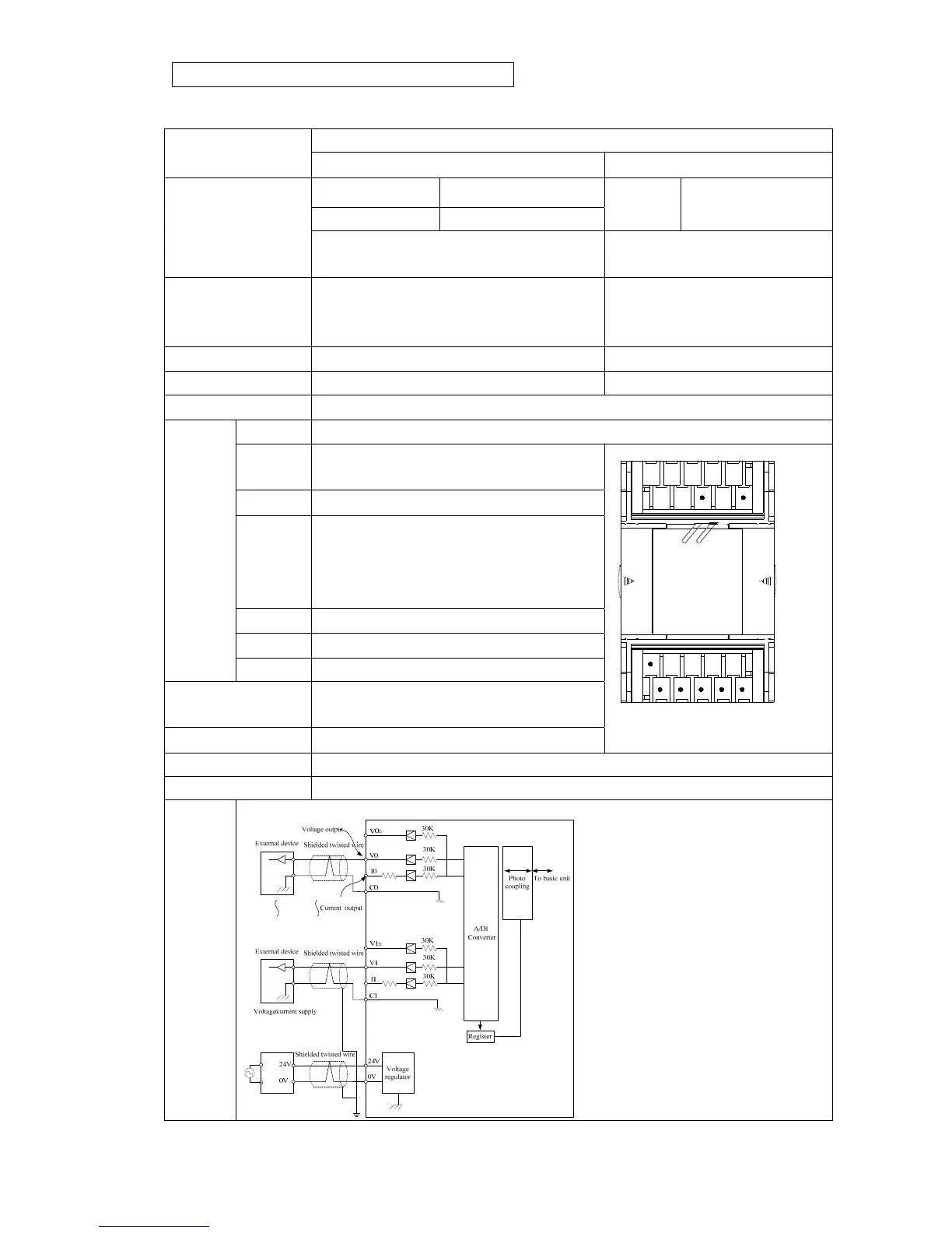
V0~V1 Voltage output terminal, output voltage signal between terminal V and C.
I0~I1 Current output terminal, output current
signal between terminal I and C
C0~C1 Common ground for V0~V2,I0~I2
V0±~
V1±
Voltage output terminal, output voltage
signal (-10V~+10V)between V and C
terminal (V0,V1 and V0±,V1± can not be
used at same time)
C2~C3 Common ground for V0±~V1±
24V 24VDCPower input terminal(+)
Terminal
block
0V 24VDCPower input terminal(-)
Power indicator
PWR:+24 V Power LED(Green)
LNK: Link LED(Green)
internal power 5VDC:Max current 30mA
V0㊣ V1㊣
C2 C3
+24V
C1V1C0V0
0V
PWR
I0
I1
LNK
Outline figure
External power 24VDC±10%(Consumption current: Max 100 mA)
Accessory Installation manual, Expansion cable(TP-304EC : 6cm, 26pin)
Principle
figure