Trial Run
Troubleshooting 6-5
c. Spare units
Prepare necessary replacement for faulty units
d. System memory setting recorder and I/O relay assignment lists.
Please prepare ‘system memory setting recorder’ and ‘I/O relay assignment lists’.
3.4 Check the following again
Power indicator
The red indicator for POWER will be on as the main unit/ expansion unit is supplied
with power. If it is off on main unit, maybe it is caused by the heavy load of built-in
DC24V on TP03. Please unload it, and prepare with external power supply DC 24V.
Preparation
Please check the wiring for input/ output and power. If AC220V is supplied to
input/ output terminals, the TP03 body will be damaged.
After send the user program (programmed by PC/ PDA) to TP03, check the
ERROR indicator. If the ERROR indicator does not blink, that means the program
is right. And the program can be trial run then.
It is available for user to enforce terminal ON or OFF with PC/ PDA to inspect
wiring.
Run and supervision
PC/ PDA can supervise the set value and present value from Timer, Counter, Data
register and enforce the output ON/OFF.。
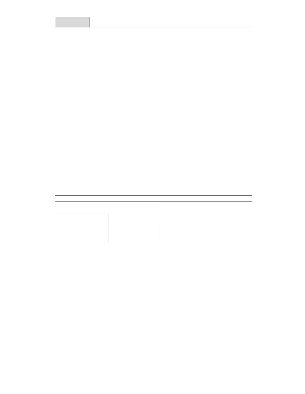
PLC input/ output responding time
Responding time for PLC from sending input signal to input terminal to output
signal: Responding time = Delay for input port +Scan time for operating user program+ Delay for
output port
Delay time for general input terminal 2.5ms, can not be adjusted.
Delay time for Interruption or high speed signal 10us, can not be adjusted.
Scan time for operating user program Please refer to D8010
Delay time for general
output terminal
Relay type: about 5ms。
Transistor type: about 15us。
Delay time for output
terminal
Delay time for pulse
output terminal of H
type.
About 5 us (only for transistor type)