Instruction list
7-2
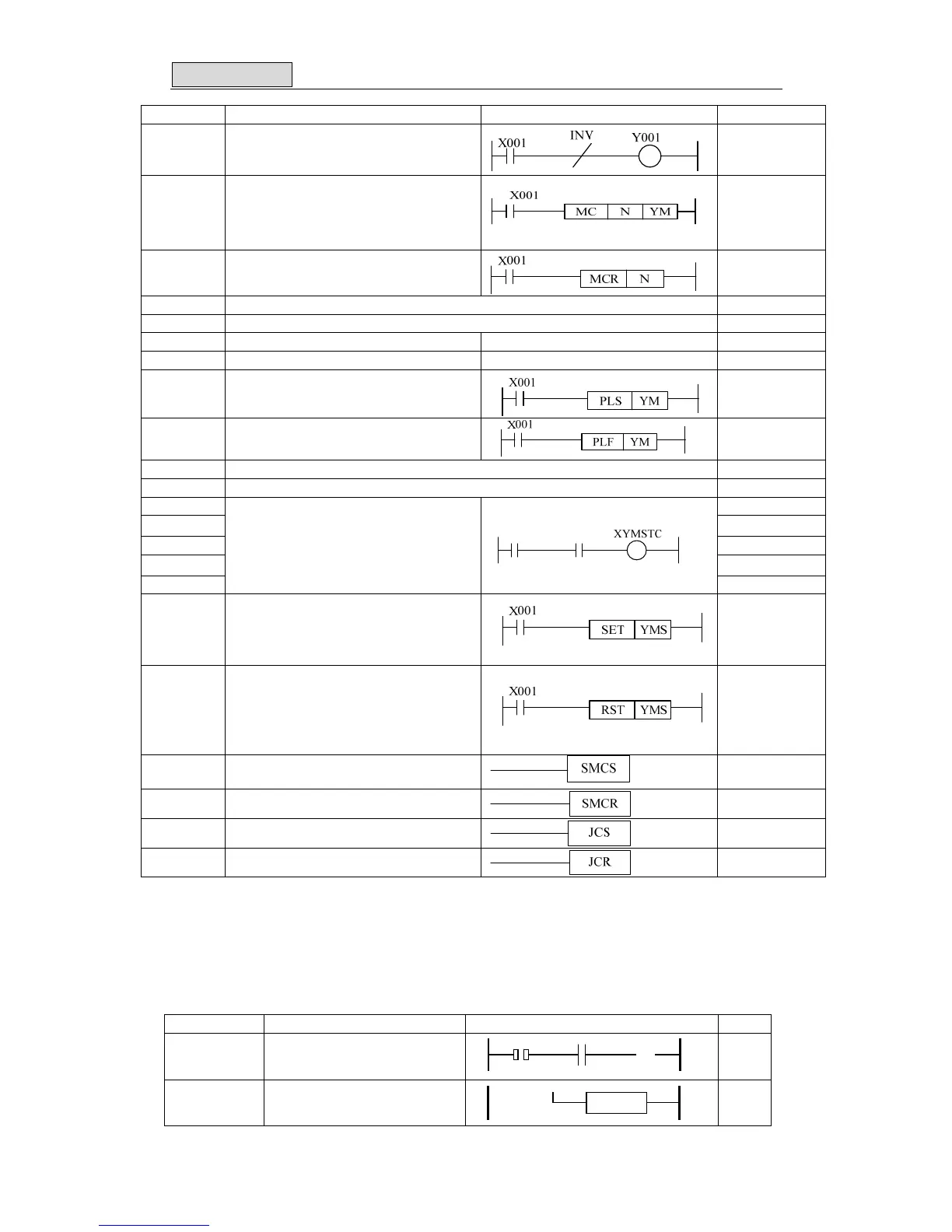
Mnemonic Function Circuit Step
[INV] Inverse
1
[MC]
Denotes the start of a master control
block
3
[MCR]
Denotes the end of a master control
block
2
[NOP] No operation 1
[END] Program End 1
[STL] Step ladder 1
[RET] Step ladder return 1
[PLS]
Rising edge pulse
2
[PLF]
Falling / trailing edge pulse
2
[P] Pointer
[I] Interruption pointer
[OUT] Y&M:1
[OUTI] 2
[OUT T] T :3
[OUT C] C :3/5
[OUT S]
Driving timer or counter coils
2
[SET]
Sets a bit device permanently ON
Y, M : 1
S, special M:2
T,C:2
special D:3
[RST]
Resets a bit device permanently OFF
Y, M : 1
S, special M:2
T,C:2
D&V&Z&
special D:3
[SMCS] Master control set
1
[SMCR] Master control reset
1
[JCS] Jump control set
1
[JCR] Jump control reset
1
Note: The step for [LD],[LDI],[AND],[ANDI],[OR],[ORI] with operand M1536~M7679 or
S1024~4095 is 2.
The step for [OUT] with operand M1536~M7679 or S is 2.
The step for [SET],[RST] with operand M1536~M7679, M8000~80511 and S is 2.
2 Step instruction :STL, RET
Mnemonic Function Circuit Step
[STL]
Step ladder