Measurement Description
Badge Results
Select which of the available switching loss measurements to display. The choices are
Power loss or Energy loss.
Ton-Start & Toff-Stop Current Level Set the Ton-Start & Toff-Stop Current Level. This control is only present when Gate Voltage
(Vg) is set to None.
Ton-Stop & Toff-Start Voltage Level Set the Ton-Stop & Toff-Start Voltage Level.
Toff-Stop Current Level Set the Toff-Stop Current Level. This control is only present when Gate Voltage (Vg) is set
to something other than None.
Global Measurement Settings
Set reference levels, gating, and Hysteresis level. See Global Measurement Settings panel
(Measurement configuration menu) on page 1
12
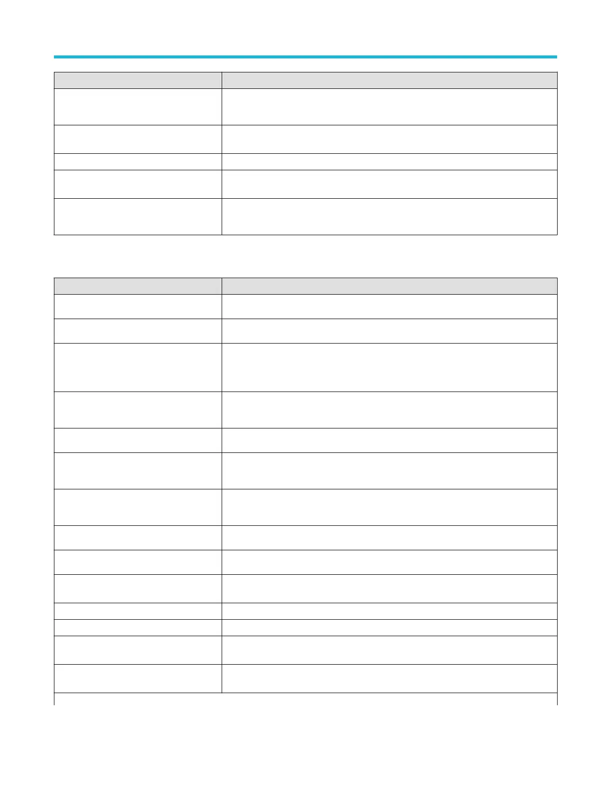
Harmonics Measurements panel (optional)
Measurement Description
Voltage Source
Select which channel the voltage waveform is on.
Current Source
Select which channel the current waveform is on.
Harmonics
Specify the number of harmonics to calculate. whether to calculate harmonics on the
voltage or the current waveform, and how to determine the frequency of the primary
waveform.
Standard
Select between general harmonics analysis or testing to a specific standard, such as IEC
61000-3-2 Class A or MIL-STD-1399 Section 300A.
Harmonics Source
Specify whether to calculate harmonics on the voltage or the current waveform.
Frequency Reference
Select how to determine the frequency of the primary waveform. Choices are None, IEC
61000-3-2, V
, I, Fixed.
Fixed Reference
Specify the fixed reference frequency of the primary waveform. This control is only
available when Frequency Reference is set to Fixed.
Display
Selects the harmonics to display.
Line Frequency
Select teh line frequency of the DUT .
Class Select the class from the drop-down list. Available values are A, B, C (Table 1), C (Table 2),
C (Table 3), and D.
Observation Period (OP) Enter the observation period.
Set Scale & RL for OP Sets the scale and record length for the observation period.
Power Factor Enter the power factor. This control is only present when Class is set to Class C, Tables 1,
2, or 3.
Current Enter the current. This control is only present when Class is set to Class C, Tables 1, 2, or
3.
Table continued…
Menus and dialog boxes
3 Series Mixed Domain Oscilloscope Printable Help 108