• The direction of the clock edge to use
•
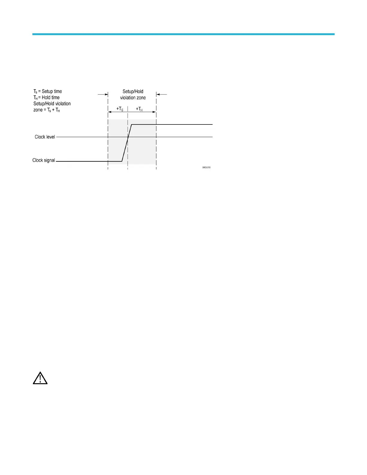
The clocking level and data threshold that the instrument uses to determine if a clock or data transition has occurred
• The setup and hold times that together define a time range relative to the clock
Data that changes state within the setup/hold violation zone triggers the instrument. The next figure shows how the setup and hold times
that you choose position the violation zone relative to the clock.
Setup/hold triggering uses the setup/hold violation zone to detect when data is unstable too near the time it is clocked. Each time trigger
holdof
f ends, the instrument monitors the data and clock sources. When a clock edge occurs, the instrument checks the data stream it is
processing (from the data source) for transitions occurring within the setup/hold violation zone. If any occur, the instrument triggers with the
trigger point located at the clock edge.
The setup/hold violation zone spans the clocking edge as shown above. The instrument detects and triggers on data that does not become
stable long enough before the clock (setup time violation) or that does not stay stable long enough after the clock (hold time violation).
Rise/Fall time trigger concepts
Rise/Fall time triggering is based on the slope (change in voltage/change in time) of a pulse edge. Trigger on pulse edges that traverse
between two thresholds at faster or slower rates than the specified time.
Use the Rise/Fall time trigger to trigger the instrument on pulse edges that traverse between two thresholds at faster or slower rates than
the specified time. You can set up the instrument to trigger on positive or negative edges.
Sequential (A B) trigger concepts
In applications that involve two or more signals, you may be able to use sequential triggering to capture more complex events. Sequential
triggering uses the A (Main) trigger to arm the trigger system, and then uses the B (Delayed) trigger to trigger the instrument if a specific
condition is met. Both the A trigger and the B trigger must be Edge triggers.
You can choose one of two trigger conditions:
• Trigger after a Delay. After the A trigger arms the trigger system, the instrument triggers on the next B-trigger event that occurs after
the trigger delay time. You can set the trigger delay time with the keypad or a multipurpose knob.
• Trigger on the Nth event. After the A trigger arms the trigger system, the instrument triggers on the Nth B event. You can set the
number of B events with the keypad or a multipurpose knob.
Note: The traditional delayed trigger mode called Runs After is controlled by the Horizontal Delay feature. Y
ou can use horizontal
delay to delay acquisition from any trigger event, whether from the A trigger alone or from a sequential trigger that uses both the A
and B triggers.
Triggering concepts
3 Series Mixed Domain Oscilloscope Printable Help 254