7. HDMI output lets you connect an external monitor or projector to show the oscilloscope screen.
8.
Security lock connector lets you use a standard PC/laptop lock cable to secure the oscilloscope to a work bench or other location.
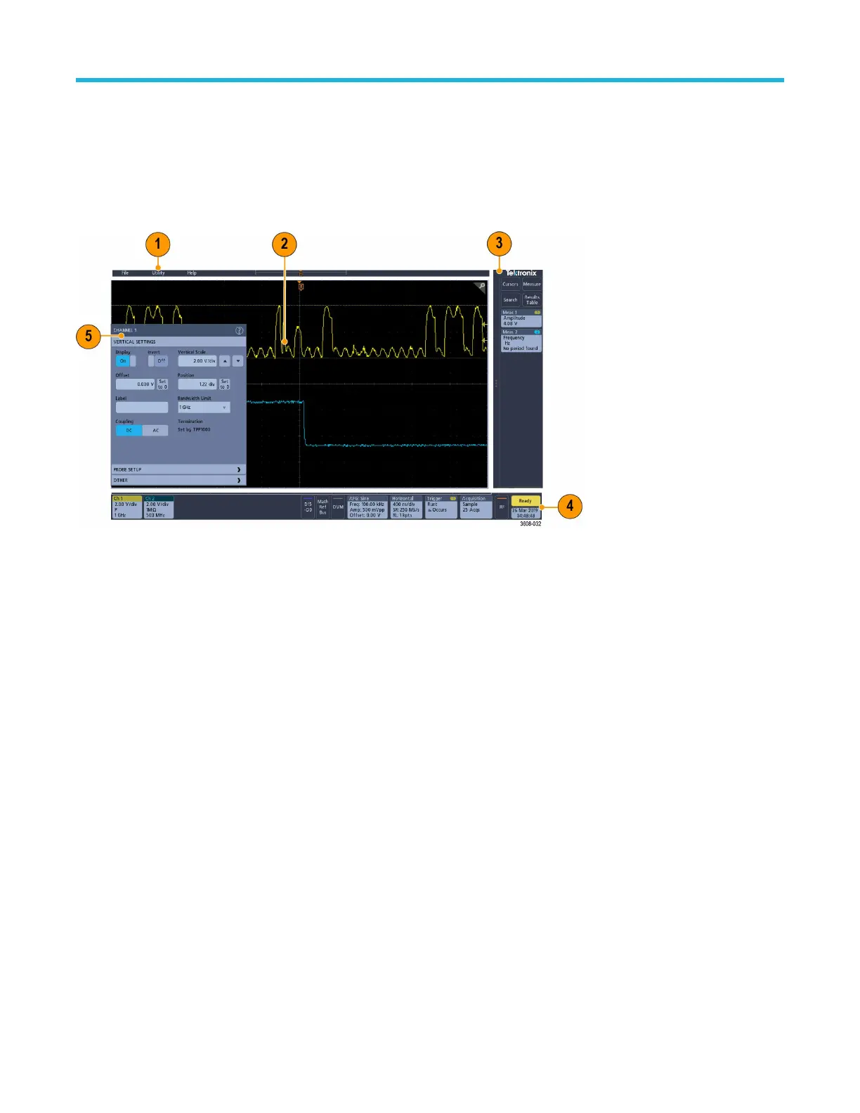
The user interface screen
The touchscreen user interface contains waveforms, measurement readouts, and touch-based controls to access all oscilloscope
functions.
1. The Menu bar provides menus for typical operations including:
•
Saving, loading, and accessing files
• Setting oscilloscope display and measurement preferences
• Configuring network access
• Running self tests
• Erasing measurement and settings memory (TekSecure™)
• Loading option licenses
• Opening a Help viewer
2. The Waveform View area displays analog, digital, math, reference, and bus waveforms. The waveforms include waveform handles
(identifiers), trigger position, and level(s) indicators. See Identifying items in the time domain display on page 45.
3. The Results Bar contains controls for displaying cursors, adding result tables to the screen, and adding measurements to the Results
bar. The controls are:
• The Cursors button displays on-screen cursors. Touch and drag or use the Multipurpose knobs to move the cursors. Double-tap
on a cursor or on the cursor readouts to open a configuration menu to set cursor types and related functions.
• The Measure button opens a configuration menu from which to select and add up to four measurements to the Results bar. Each
measurement you add has a separate badge. Double-tap a measurement badge to open its configuration menu.
• The Results Table button adds a Measurement, Bus, Search, and Harmonics results table to the screen. The Measure tab
displays all measurements present in the Results bar. The Bus tab displays bus decode information for displayed bus waveforms.
The Search tab displays search event information. The Harmonics tab displays harmonic measurement results.
• The Search button lets you detect and mark a waveform where specified events occur. Tap Search to open a Search configuration
menu and set the search conditions for analog and digital channels. Search badges are added to the Results Bar.
• The Measurement and Search badges show measurement and search results and are displayed in the Results Bar. See
Badges on page 50. See Add a measurement on page 72. See Add a search on page 76.
4. The Settings Bar contains System badges for setting Horizontal, Trigger, Acquisition, and Date/Time parameters; Inactive Channel
buttons to turn on channels; Math/Ref/Bus button to add math, reference, and bus waveforms to the display; and Channel and
Getting acquainted with your instrument
3 Series Mixed Domain Oscilloscope Printable Help 44