When acquisitions are stopped, you can navigate through the history of the spectrogram by pressing the side menu slice control and
turning the Multipurpose a knob. When acquisitions are stopped and the spectrogram is displayed, the spectrogram slice trace is displayed
as the Normal spectrum trace.
T
o use the spectrogram feature, display a trace in RF mode.
1. Double-tap the RF badge to display the RF menu.
2. Tap Traces to display the traces panel.
3. Tap Spectrogram to toggle the spectrogram display on.
4. To review each spectrum captured in the spectrogram, push Run / Stop to stop acquiring RF acquisitions. Turn Multipurpose knob a.
Automatic peak markers
This topic explains the automatic peak markers in the RF mode display.
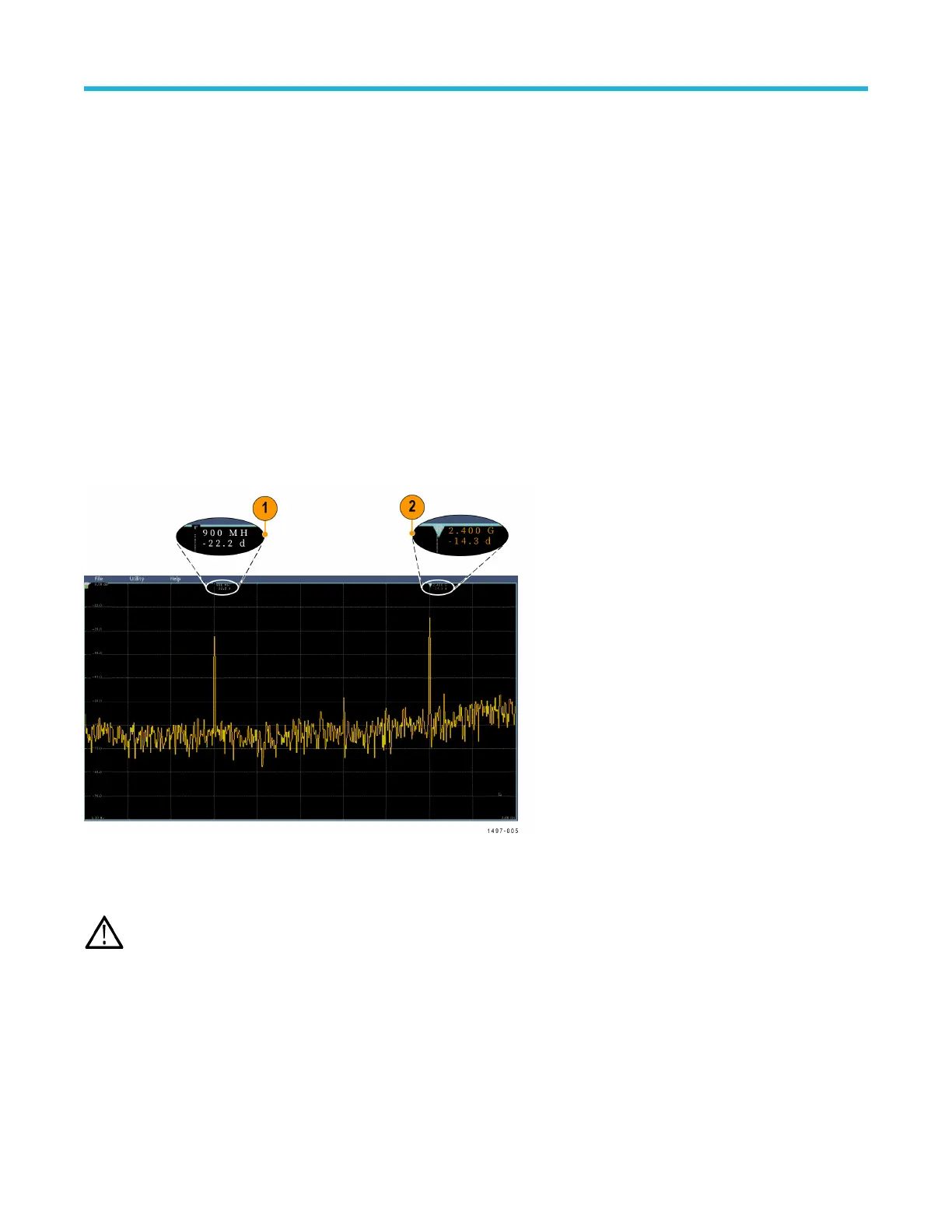
Automatic peak markers are on by default and assist with quickly identifying the frequency and amplitude of peaks in the spectrum.
1. The Reference Marker is placed on the highest amplitude peak. It is marked with a red R in a triangle.
2. The automatic markers indicate frequency and amplitude.
3. Absolute readouts show the actual frequency and amplitude of the automatic markers.
4. Delta readouts show the frequency and amplitude of the automatic markers relative to the reference marker.
Each automatic marker has a readout associated with it. These can be absolute or delta readouts. An absolute marker readout shows the
actual frequency and amplitude of the associated marker
. A delta marker readout shows the frequency and amplitude differences from the
Reference Marker. The Reference Marker’s readout indicates absolute frequency and amplitude, regardless of the readout type.
Note: Automatic markers can be turned on and of
f in the Waveform View menu. Tap Peak Markers to toggle the automatic
markers on and off.
Frequency domain cursors
This topic provides help in using frequency domain cursors.
T
wo cursors are provided to measure non-peak areas of the spectrum and to measure Noise Density and Phase Noise. When the
cursors are turned on, the Reference Marker is no longer automatically attached to the highest amplitude peak. It is now assigned to the
Multipurpose knob a and can be moved to any location. This enables easy measurement of any part of the spectrum as well as delta
Waveform acquisition concepts
3 Series Mixed Domain Oscilloscope Printable Help 245