ARINC429 serial bus menu
Use the ARINC429 bus menu (optional) to set up and decode an ARINC429 avionics network serial bus.
T
o decode an ARINC429 serial bus:
• Tap the Add Math Ref Bus badge on the Settings bar and select Bus1 or Bus2. Open the bus configuration menu by double clicking
on the new Bus badge. Set the Bus Type to ARINC429.
• To change the settings on an existing ARINC429 serial bus waveform, double-tap the Bus waveform badge and make necessary
changes.
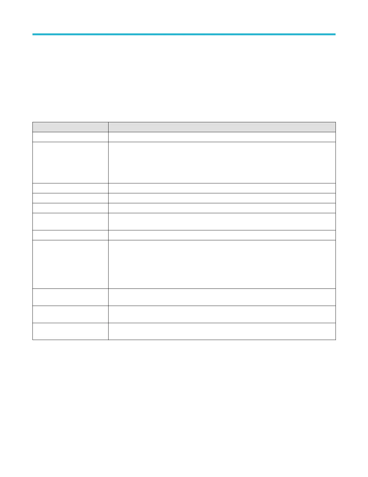
ARINC429 serial bus menu fields and controls
Field or control Description
Display Turns on or off displaying the bus in the Waveform view.
Label Enter a label for the bus. The default label is the selected bus type.
T
o enter label text, double-tap the field and enter label using the virtual keyboard, or tap the field and
enter text using an attached keyboard.
Bus Type Set to ARINC429.
Polarity Select the polarity to match the ARINC429 bus being acquired.
Source Select the ARINC429 signal source.
High Threshold, Low
Threshold
Sets the valid high and low threshold values for the signal source.
Bit Rate Sets the bit rate to 12,500, 100,000, or Custom.
Custom Rate Sets a custom data bit rate. To set the value, tap the field and use the Multipurpose knob, double-tap
the field and use the Custom Rate virtual keypad, or double-tap the field and use an attached
keyboard.
This field is only visible when Bit Rate = Custom.
Data Format Sets the data format to Data (19 bits), SDI (Source/Destination Identifiers) plus Data (21 bits), or SDI
plus Data plus Sign/Status Matrix (SSM) (23 bits).
Display Format Sets the waveform view to show just the decoded bus information, or the decoded bus and the logical
views of each constituent signal.
Decode Format Sets the decode format used to display the bus information. Formats are Hex, Binary, and Mixed Hex.
Mixed Hex displays labels as octal, and other fields are formatted as hexadecimal.
Other bus types
Serial bus types, such as CAN, LIN, Ethernet, and so on, are available as purchasable options. Once purchased and installed, the new bus
types are shown in the Bus T
ype menu. The serial bus options also add corresponding bus trigger capabilities to the Trigger menu.
Use the following links to access information on specific Bus configuration menus.
Parallel Bus configuration menu on page 127
I2C serial bus configuration menu on page 123
SPI serial bus configuration menu on page 131
RS-232 serial bus menu on page 129
Menus and dialog boxes
3 Series Mixed Domain Oscilloscope Printable Help 117