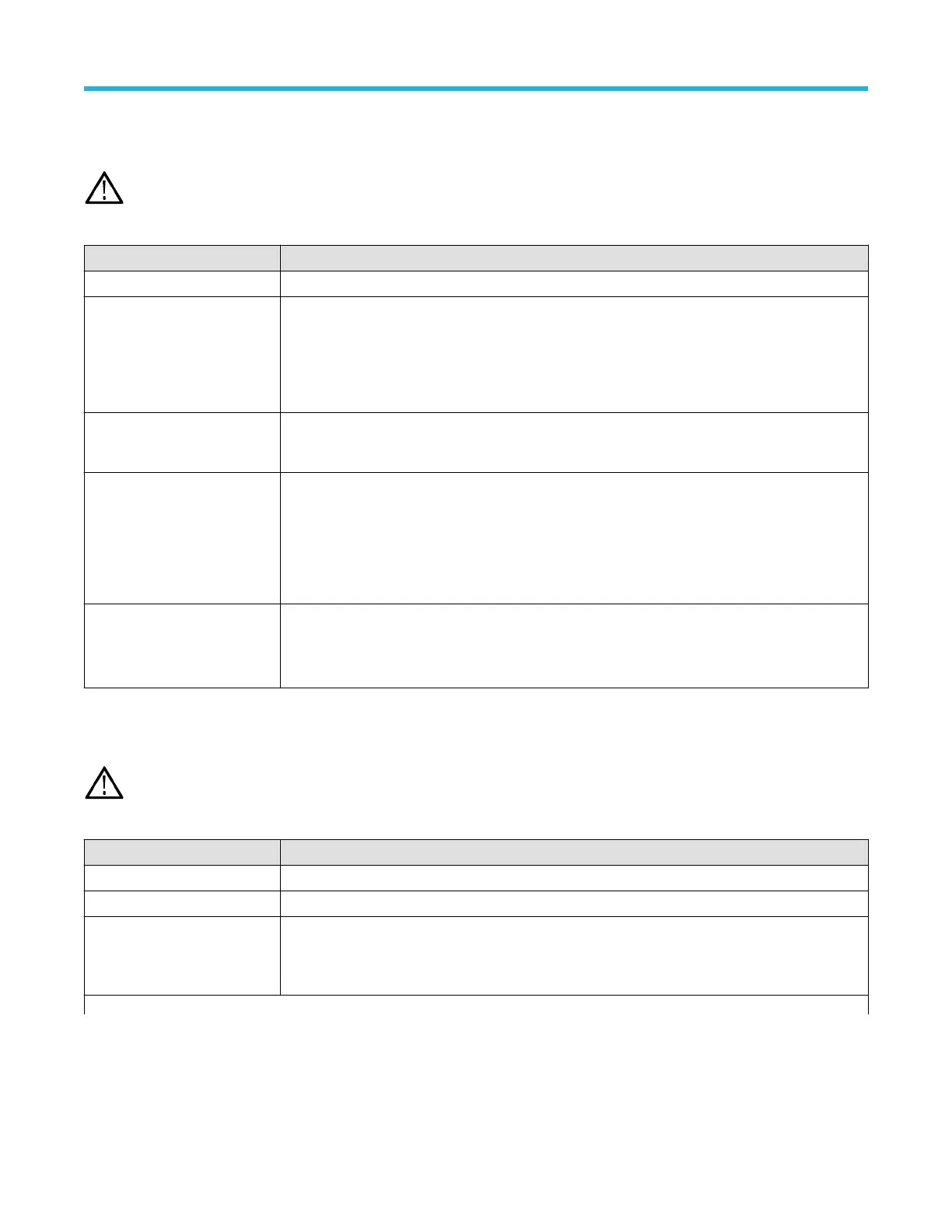
Parallel serial bus trigger settings panel
Use this menu to set up and display a parallel bus waveform.
Note: Parallel bus triggering is standard on all instruments.
Field or control Description
Source Select the type of information on which to trigger.
Data Sets the data pattern on which to trigger. The number of bits shown depends on how the parallel bus is
defined.
T
ap the Binary or Hex field and use the A and B knobs to select and change the values. Or double-tap
on the field and use the virtual keypad to enter values. See Binary, decimal, hex, and octal virtual
keypads on page 228.
A, B knob controls Use the A knob to select (highlight) the digit(s) to change.
Use the B knob to change the value of the digit(s).
Mode & Holdoff
Trigger Mode determines how the instrument behaves in the absence or presence of a trigger event.
Holdoff sets the amount of time the oscilloscope waits after a trigger event before detecting and
triggering on the next trigger event.
For additional information on Trigger Mode, Holdoff, forcing a trigger, and the Trigger Frequency
Counter see Mode and Holdoff panel on page 226.
Act On Trigger
Set the actions the instrument takes when a trigger event occurs.
For additional information on the Act On Trigger panel see Act On Trigger configuration
menu on page 227.
RS-232 serial bus trigger settings panel
Use this menu (optional) to set up and display an RS232 serial bus waveform.
Note: Requires option SRCOMP
.
Field or control Description
Source Select the RS-232 bus on which to trigger
.
Trigger On Select the type of information on which to trigger.
Data Bytes Sets the number of data bytes (1 byte = 8 bits) on which to trigger (one to ten bytes). Use the A knob
to change the value.
Available when Trigger On = Rx Data or Tx Data.
Table continued…
Menus and dialog boxes
3 Series Mixed Domain Oscilloscope Printable Help 211