Triggering
3-64
TDS5000 Series User Manual
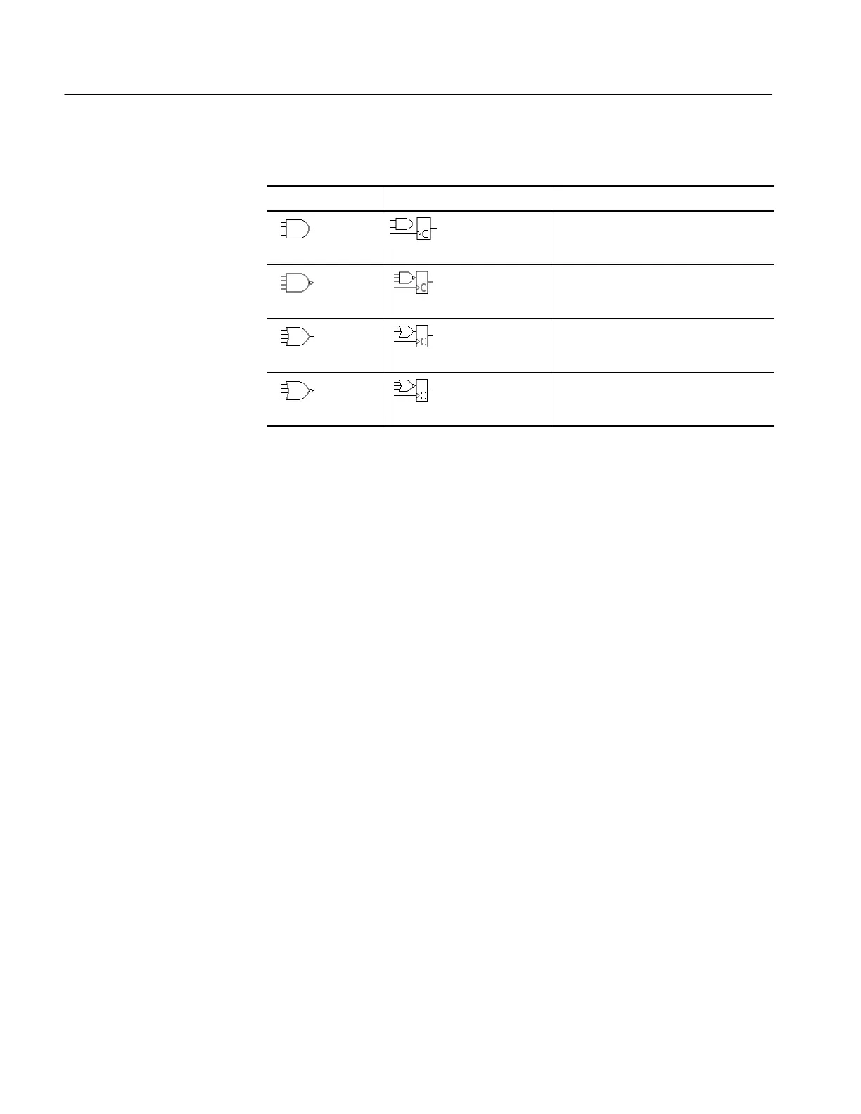
Table 3- 5: Pattern and state logic
Pattern State Definition
1, 2
AND Clocked AND If all the preconditions selected for the
logic inputs
3
are TRUE, then the
oscilloscope triggers.
NAND Clocked NAND If not all of the preconditions selected
for the logic inputs
3
are TRUE, then the
oscilloscope triggers.
OR Clocked OR If any of the preconditions selected for
the logic inputs
3
are TRUE, then the
oscilloscope triggers.
NOR Clocked NOR If none of the preconditions selected for
the logic inputs
3
are TRUE, then the
oscilloscope triggers.
1
For state triggers, the definition must be met at the time the clock input changes
state.
2
The definitions given here are correct for the Goes TRUE setting in the Trigger When
menu. If that menu is set to Goes False, swap the definition for AND with that for
NAND and for OR with NOR for both pattern and state types.
3
The logic inputs are channel s 1, 2, 3, and 4 when using Pattern triggers. For State
triggers, channel 4 becomes the clock input, leaving the remaining channels as logic
inputs. (On the TDS5052, channel 2 is the cl ock input.)
 Loading...


