Triggering
3-82
TDS5000 Series User Manual
Use this procedure to trigger the oscilloscope when all of the logic inputs to the
selected logic function cause the function to be True or False when the clock
(channel 4) input changes state. (The clock input is channel 2 on the TDS5052.)
Overview To trigger on state Control elements and resources
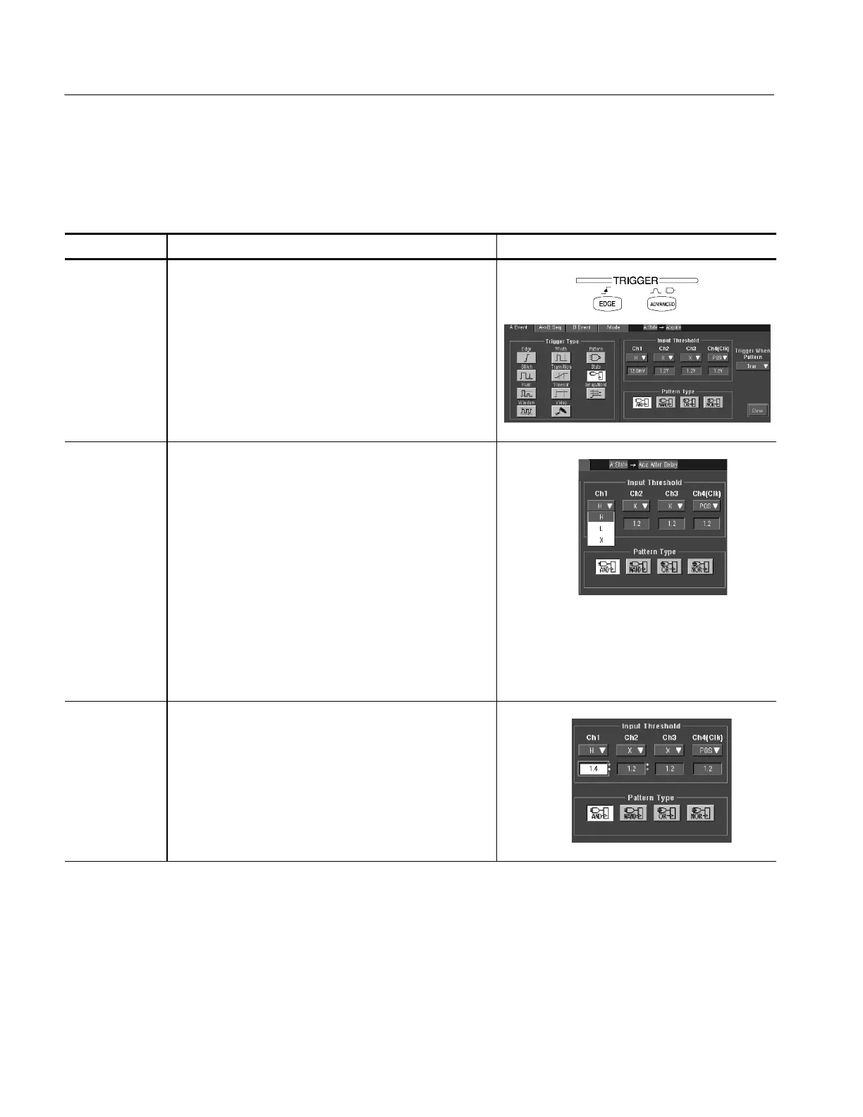
Select state
triggering
1. Push the front-panel ADVANCED button.
2. On the Trigger Setup control window, select the A Event
tab.
3. Click State.
Define state
inputs
4. Select an input val ue from the drop-down list for each
channel. Channels 1, 2, and 3 represent the data inputs
(Channel 1 only on the TDS5052). Channel 4 (Channel
2 on the TDS5052) should be connected to the clock
signal.
The channel inputs combine to form a logic pattern.
Each channel can have a value of high (H), low (L), or
”don’t care” (X). A value is considered high if the
channel input voltage is greater t han the specified
threshold voltage; a value is considered low if the
channel input voltage is less than the specified threshold
voltage. Use the ”don’t care” selection for any channels
that will not be used as part of the pattern.
Set threshold
voltages
5. To set the threshold voltages, cl ick on the channel
threshold control and use the multipurpose knobs or
pop-up keypad to set each threshold.
Triggering on Logic State
 Loading...


