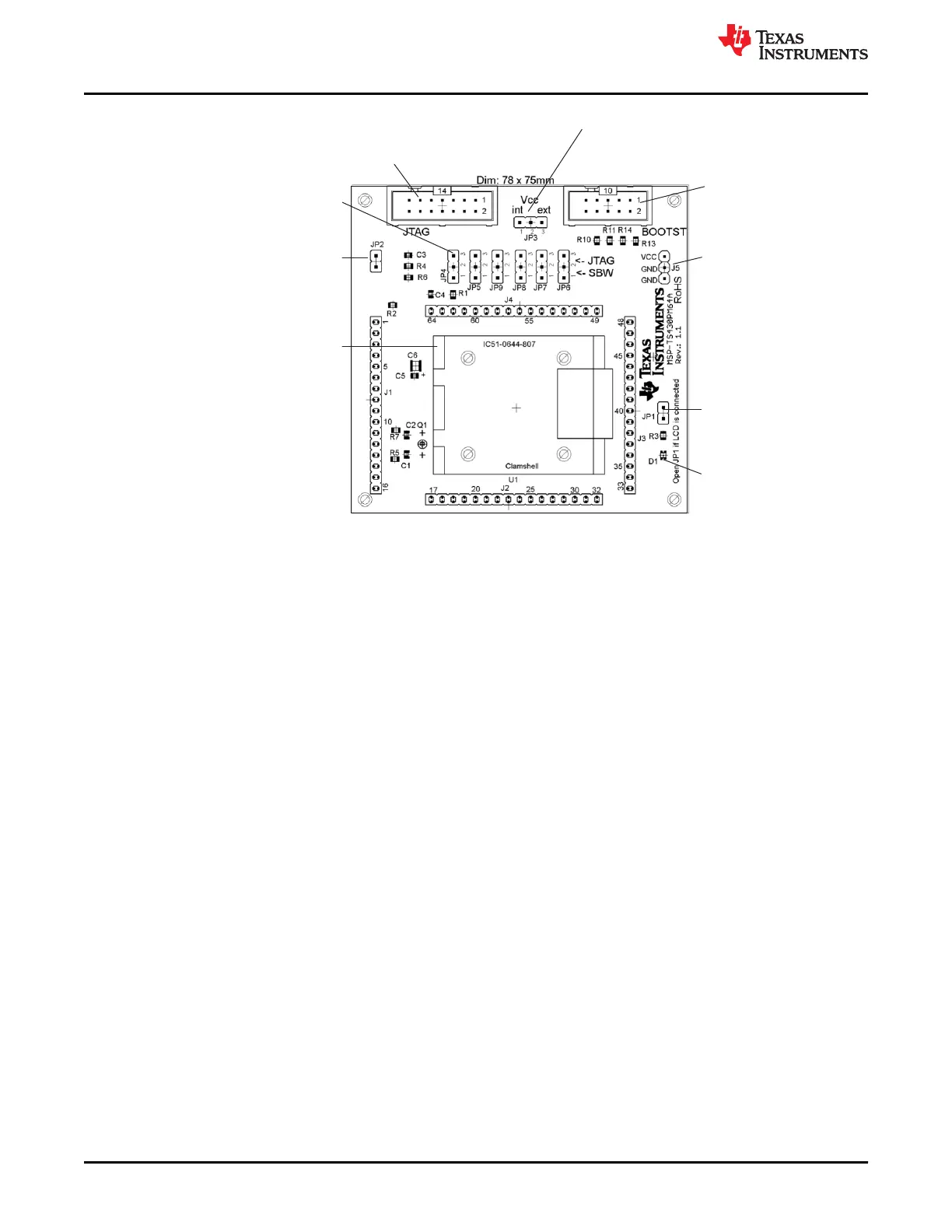
Jumper JP2
Open to measure current
Jumper JP1
Open to disconnect LED
D1
LED connected to P5.1
Jumper JP3
1-2 (int): Power supply from JTAG interface
2-3 (ext): External power supply
Jumpers JP4 to JP9
Close 1-2 to debug in Spy-Bi-Wire mode
Close 2-3 to debug in 4-wire JTAG mode
Orient Pin 1 of MSP430 device
Connector JTAG
For JTAG Tool
Connector BOOTST
For Bootloader Tool
Connector J5
External power connector
Jumper JP3 to "ext"
Figure B-47. MSP-TS430PM64A Target Socket Module, PCB
Hardware
www.ti.com
102 MSP430™ Hardware Tools SLAU278AG – MAY 2009 – REVISED DECEMBER 2020
Submit Document Feedback
Copyright © 2020 Texas Instruments Incorporated

 Loading...


