14
1
2
10
1
2
IC51-0644-807
Clamshell
1 5 10
15
202530
35
40
45
50 55 60
R1
C11
D1
R10
D2
R11
D3
U1
J3
J4
J5
J6
R7
R15
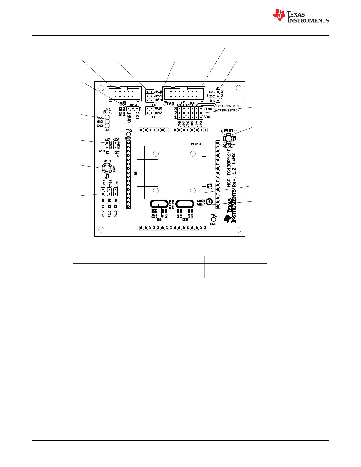
Jumper J1
1-2 (int): Power supply from JTAG interface
2-3 (ext): External power supply
Orient Pin 1 of MSP430 device
LEDs connected to
P1.0, P1.1, P1.2 from
JP9, JP10, JP11
(only D1 assembled)
Switch SW2
Connected to P1.3
Switch SW1
Device reset
Connector J2
External power connector
Jumper J1 to “ext”
HF and LF oscillators with capacitors
and resistors to connect pinheads
Connector JTAG
For JTAG Tool
Connector BSL
For Bootloader
Jumper JP1, JP2
Open to measure
digital or analog current
Jumper JP3 to JP8
Close 1-2 to debug in Spy-Bi-Wire mode
Close 2-3 to debug in 4-wire JTAG mode
BSL Tool Select
Jumper JP13 to JP15
Open = BSL Connector
Close = JTAG Connector
Close JP17 and JP18
to enable BSL pullups
BSL Interface Select
Jumper J16
Close 1-2 for I C
Close 2-3 for UART
2
Jumper Configuration UART BSL Configuration I C BSL Configuration
2
JP17 and JP18
Open
Close
JP16
Close 2-3 (UART) Close 1-2 (I2C)
This target board supports UART or I C BSL configuration. To select the configuration to use, set the
jumpers as shown in the following table.
2
Figure B-51. MSP-TS430PM64F Target Socket Module, PCB

 Loading...


