For use of BSL: connect pin 1 of BOOST to pin 58 of U1 and pin 3 of BOOST to pin 57 of U1.
Figure B-58. MSP-TS430PN80 Target Socket Module, Schematic
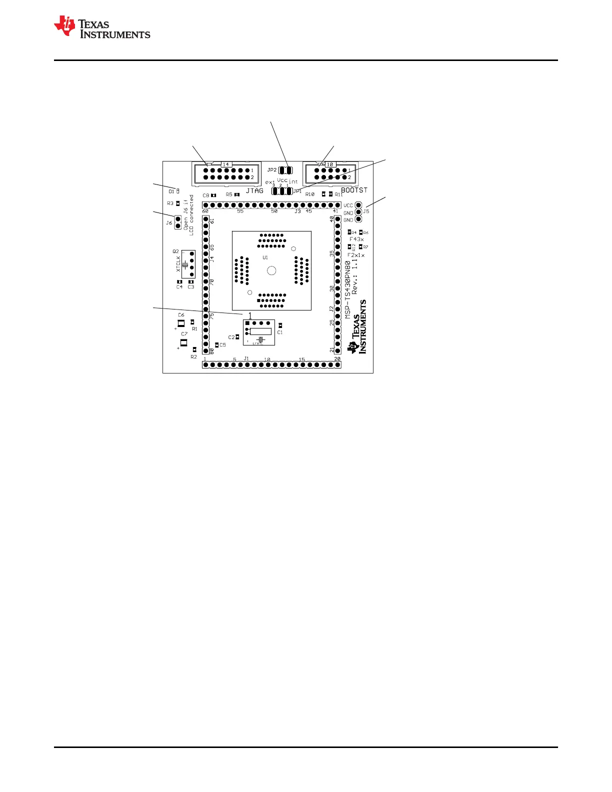
Connector J5
External power connector
Jumper JP1 to "ext"
D1
LED connected to pin 12
Jumper J6
Open to disconnect LED
Orient Pin 1 of
MSP430 device
Connector JTAG
For JTAG Tool
Connector BOOTST
For Bootloader Tool
Jumper JP1
1-2 (int): Power supply from JTAG interface
2-3 (ext): External power supply
Jumper JP2
Open to measure current
Figure B-59. MSP-TS430PN80 Target Socket Module, PCB
www.ti.com
Hardware
SLAU278AG – MAY 2009 – REVISED DECEMBER 2020
Submit Document Feedback
MSP430™ Hardware Tools 123
Copyright © 2020 Texas Instruments Incorporated

 Loading...


