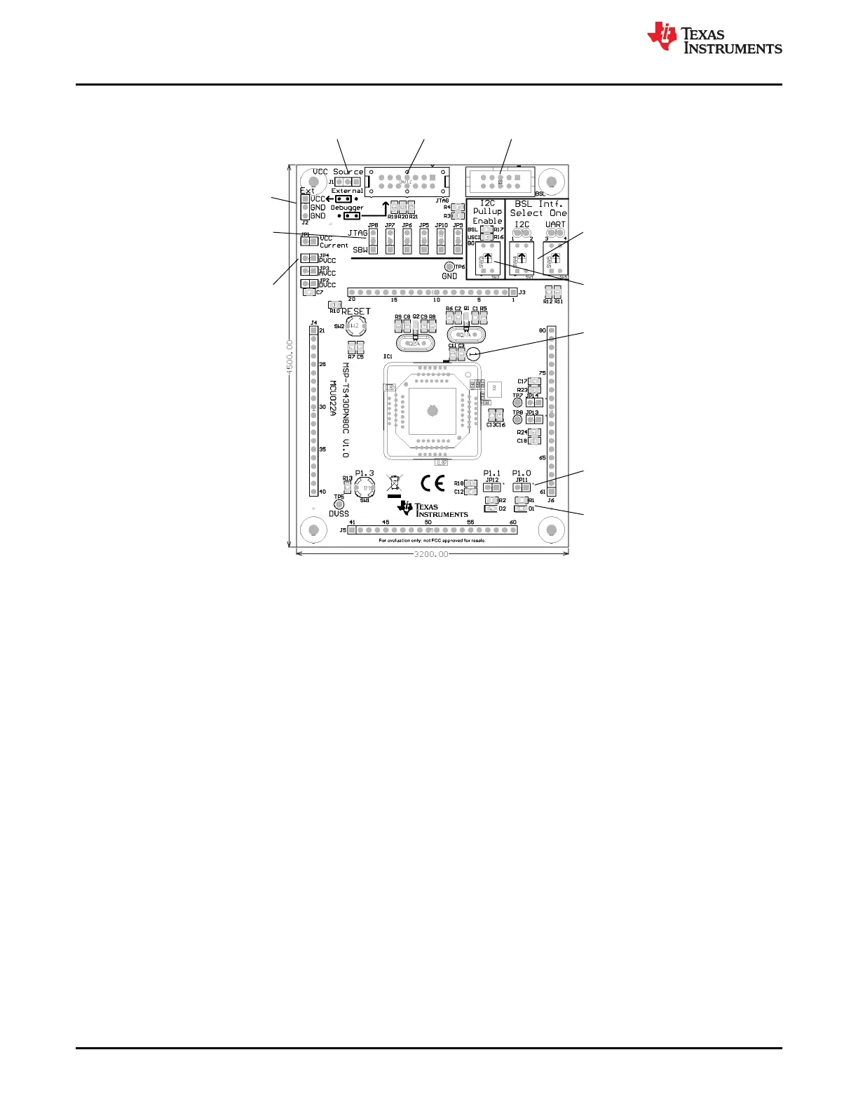
EasyManuals Logo

Texas Instruments MSP430 series User Manual

Texas Instruments MSP430 series
191 pages
To Next Page IconTo Next Page
To Previous Page IconTo Previous Page
Page #132 background imageLoading...
Page #132 background image
Connector JTAG
For JTAG Tool
Connector BSL
For Bootloader Tool
Jumper J1
1-2 (Debugger): Power supply from JTAG Interface
2-3 (External): External power supply
Connector J2
External power connector
Jumper J1 to External
Jumpers JP5 to JP10
Close 1-2 to debug in Spy-Bi-Wire mode
Close 2-3 to debug in 4-wire JTAG mode
Jumpers JP1 to JP4
Open to measure current
BSL Interface Switches
Select which BSL interface to connect to
connector BSL
I2C pullup enable switch
Switch On to connect I2C pullup resistors
Orient Pin 1 of MSP430 device
Jumpers JP11 and JP12
Open to disconnect LEDs D1 and D2
D1, D2
LEDs connected to P1.0, P1.1
Figure B-65. MSP-TS430PN80C Target Socket Module, PCB
Hardware
www.ti.com
132 MSP430™ Hardware Tools SLAU278AG – MAY 2009 – REVISED DECEMBER 2020
Submit Document Feedback
Copyright © 2020 Texas Instruments Incorporated

Table of Contents

Other manuals for Texas Instruments MSP430 series

Questions and Answers:

Question and Answer IconNeed help?

Do you have a question about the Texas Instruments MSP430 series and is the answer not in the manual?

Texas Instruments MSP430 series Specifications

General IconGeneral
BrandTexas Instruments
ModelMSP430 series
CategoryMicrocontrollers
LanguageEnglish

Related product manuals