EasyManua.ls Logo

Texas Instruments MSP430 series User Manual

Texas Instruments MSP430 series
191 pages
To Next Page IconTo Next Page
To Previous Page IconTo Previous Page
Page #172 background image
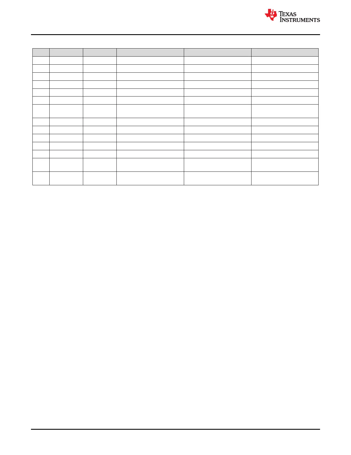
Table B-43. MSP-TS430PZ100AUSB Bill of Materials (continued)
Pos. Ref Des No. Per Board Description Digi-Key Part No. Comment
36 R14 1 0 Ohm, SMD0805 541-0.0ATR-ND
37 R3 1 330 Ohm, SMD0805 541-330ATR-ND
38 R33 1 1k4 / 1k5 SMD0603 Buerklin: 07E612
39 R34, R35 2 27R SMD0603 Buerklin: 07E444
40 R36 1 33k SMD0603 Buerklin: 07E740
41 R5 1 47k Ohm, SMD0805 541-47000ATR-ND
42
R6, R8, R9,
R12
4 0 Ohm, SMD0805 541-000ATR-ND DNP
43 S1, S2 1 PB P12225STB-ND DNP
44 S3 1 PB P12225STB-ND
45 TP1, TP2 2 Test point DNP, Keep vias free of solder
46 U1 1 Socket: IC357-1004-53N Manuf.: Yamaichi
47 USB1 1 USB Receptacle FARNELL: 117-7885
48
Insulating disk
for Q2
1 Insulating disk for Q2 ettinger.de 70.08.121
49
Rubber stand
off
4 Buerklin: 20H1724 Apply to corners at bottom side
Hardware
www.ti.com
172 MSP430™ Hardware Tools SLAU278AG – MAY 2009 – REVISED DECEMBER 2020
Submit Document Feedback
Copyright © 2020 Texas Instruments Incorporated

Table of Contents

Other manuals for Texas Instruments MSP430 series

Question and Answer IconNeed help?

Do you have a question about the Texas Instruments MSP430 series and is the answer not in the manual?

Texas Instruments MSP430 series Specifications

General IconGeneral
Program Memory TypeFlash
CPU CoreMSP430
Clock SpeedUp to 25 MHz
Flash MemoryUp to 512 KB (depending on specific device)
RAMUp to 66 KB (depending on specific device)
Operating Voltage1.8V to 3.6V
ADC10-bit or 12-bit
Communication InterfacesUART, SPI, I2C, USB
Temperature Range-40°C to +85°C
Timers16-bit timers
Architecture16-bit RISC
Low Power ModesMultiple (LPM0 to LPM4)

Summary

Read This First

Information About Cautions and Warnings

Details on understanding and interpreting caution and warning statements for user protection.

Chapter 1: Get Started Now!

1.1 Kit Contents, MSP-TS430xx

Lists the components included in the MSP-TS430xx kit for specific target socket modules.

1.4 Kit Contents, MSP-FET430UIF

Lists the components included in the MSP-FET430UIF kit, featuring a USB interface.

1.6 Kit Contents, eZ430-F2013

Lists the components included in the eZ430-F2013 kit, a USB stick form factor interface.

1.14 Hardware Installation, MSP-FET and MSP-FET430UIF

Instructions for installing the hardware for MSP-FET and MSP-FET430UIF debuggers.

Chapter 2: Design Considerations for In-Circuit Programming

2.1 Signal Connections for In-System Programming and Debugging

Details signal requirements and connections for in-system programming and debugging using JTAG.

Appendix C: Hardware Installation Guide

Related product manuals