106
BRAKES
Read all of SAFETY and this section before attempting any procedure. Pay particular attention to Notices, Cautions, Warnings and Dangers.
Tighten the lock nut to the torque value specified below.
Brake Shoe and Adjuster Replacement
It is recommended that when brake shoes are replaced,
the adjusters and springs also be replaced. It is good
practice to do one side at a time, using the other side for
reference.
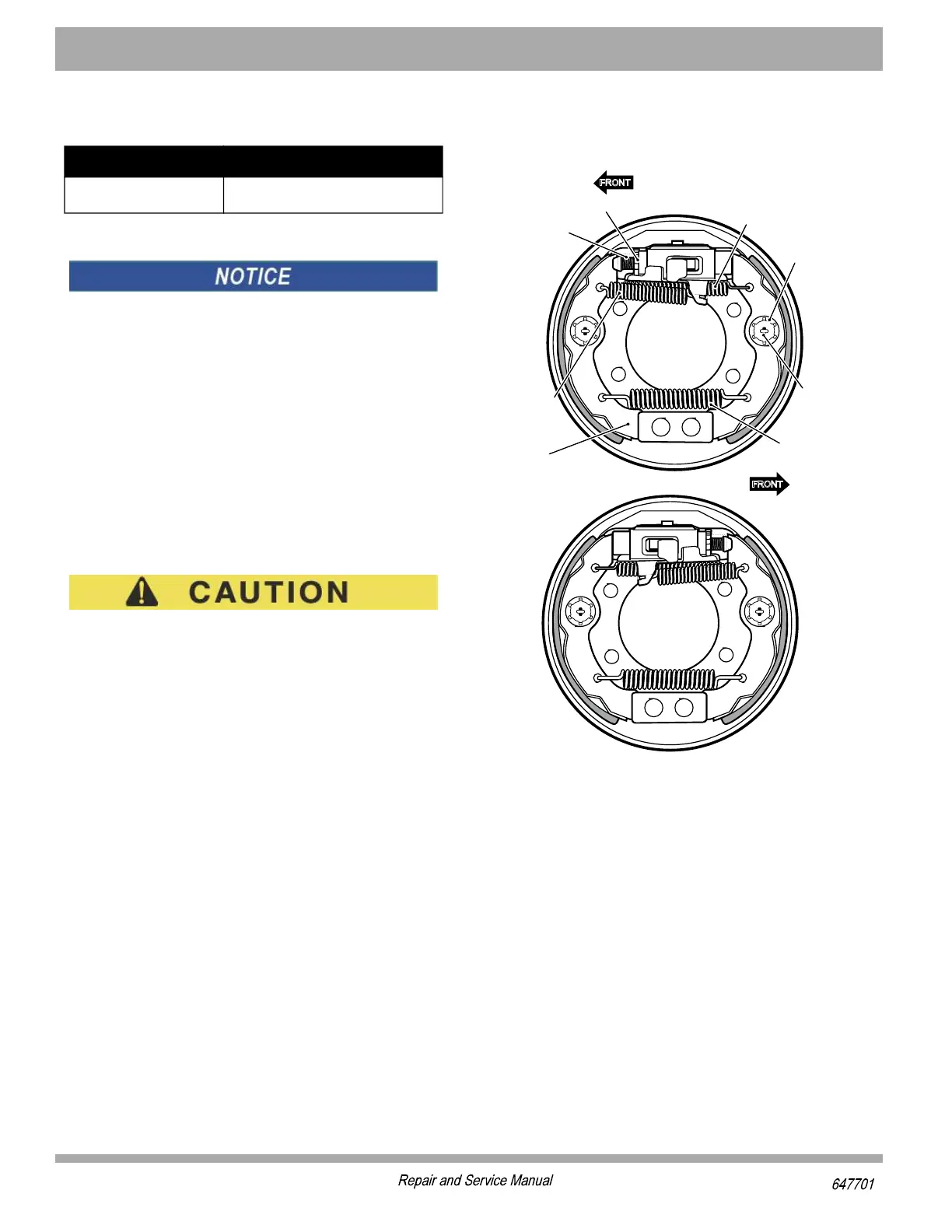
Remove the three brake shoe springs and discard (1, 2,
3). Note the location of the heavy spring and the adjuster
spring (Figure 14). Hold the shoe clamp pin (4) and com-
press and rotate the shoe clamp (5) 90° to release it from
the shoe clamp pin. Remove the brake shoes, adjuster
and remaining components.
Clean the backing plate with a commercial brake cleaner.
Allow to dry completely. Lubricate the friction points of the
shoes and moving anchor with Multi Purpose Grease
(MPG) lubricant (Figure 12).
Be sure that the adjusting screw is threaded into the
star wheel nut until only 1 - 2 threads are exposed.
Install adjuster mechanism (driver side silver, passenger
side gold). Make sure that the two Teflon coated washers
are installed as shown (Figure 12). The adjusting screw
must be threaded into the star wheel nut until only 1 - 2
threads are exposed (Figure 15).
Install the actuator piston. Make sure the hardened shim
washer is installed as shown (Figure 12).
Always replace both brake shoes on both wheels as a
set. Install the shoes as indicated and install the shoe
clamp (5) over the shoe clamp pin (4) and rotate 90° to
lock them in place (Figure 14).
Install new brake shoe and adjuster springs. The hooked
end of the adjuster spring is installed through the front of
the front shoe as shown (Figure 14). The opposite end of
the adjuster spring is connected to the adjuster with the
hook end facing out. The brake shoe springs must be
installed with the light spring closest to the adjuster mech-
anism with the hook installed down through the rear brake
shoe and up through the front brake shoe. The heavy top
spring is installed with both spring hooks installed down
through the brake shoes. Make sure that the brake oper-
ates correctly.
Install the brake drum. See Brake Drum Removal and Instal-
lation.
Repeat on other side of vehicle.
Adjust the brake pedal free travel. See ’Adjusting Brake
Pedal Free Travel’.
Figure 14 Brake Shoes and Springs
Item Torque Specification
2
23 - 28 ft. lbs. (31 - 38 Nm)
*6328
*6328
7LSI
'PEQT
7XEV[LIIP
&VEOI7LSI
(6-:)67-()&6%/)
4%77)2+)67-()&6%/)
7LSI
'PEQT4MR
%HNYWXIV
7TVMRK
,IEZ]
7LSI7TVMRK
0MKLX
7LSI7TVMRK
%HNYWXIV
7GVI[

 Loading...