FRONT SUSPENSION AND STEERING
Read all of SAFETY and this section before attempting any procedure. Pay particular attention to Notices, Cautions, Warnings and Dangers.
33
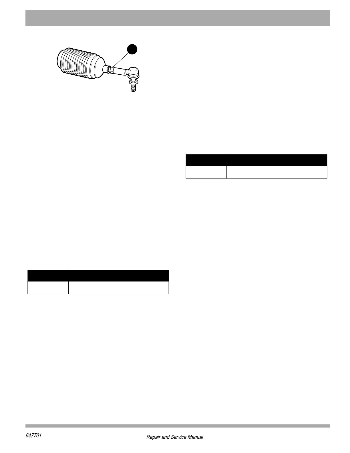
Figure 4 Tie Rod Jam Nut
Hub Assembly
Tool List Qty.
Socket, 24 mm ............................................................ 1
Ratchet........................................................................ 1
Torque Wrench, ft. lbs. ................................................ 1
Flat Blade Screwdriver ................................................ 1
Ball Peen Hammer ...................................................... 1
Remove the front wheel(s) as described in the WHEELS
AND TIRES section.
1. Remove the dust cap (1) by tapping around the cap
flange using a flat blade screwdriver and a ball peen
hammer (Figure 5).
2. Remove the lock nut (2).
3. Remove hub (3) by sliding it off of the spindle.
4. Clean spindle (4) thoroughly with solvent and inspect
spindle threads. If threads are damaged, replace the
spindle.
Installation is reverse order of removal. Replace worn or
damaged hardware as required. Lock nuts must be
replaced after a maximum of five removals
Spindle Assembly
Tool List Qty.
Wrench, 16 mm........................................................... 1
Socket, 16 mm ............................................................ 1
Socket, 18 mm Deep-well ........................................... 1
Ratchet........................................................................ 1
Torque Wrench, ft. lbs. ................................................ 1
Ball Joint Separator ..................................................... 1
Ball Peen Hammer ...................................................... 1
Remove the front wheel(s) as described in the WHEELS
AND TIRES section.
1. Remove the hub assembly as described in the previ-
ous section.
2. Loosen the nut (21) securing the tie rod end (22) to
the spindle arm until it is flush with the end of the tie
rod end (Figure 5).
3. Using a ball joint separator as a lever, apply pressure
to the ball joint and tap the spindle arm sharply with
the hammer to release the tie rod end from the spin-
dle arm.
4. Remove the nut (21) and the tie rod end (22) from
the spindle arm.
5. Remove hex nut (9) and hex head bolt (8), remove
the spindle assembly (4 and 5).
Install hub assembly in the reverse order of removal.
Replace worn or damaged hardware as required. Lock
nuts must be replaced after a maximum of five removals.
Tighten nut (9) to torque value specified below.
Struts
Tool List Qty.
Wrench, 15mm ............................................................1
Socket, 15mm Deep-Well ............................................1
Ratchet ........................................................................1
Torque Wrench, ft. lbs..................................................1
Remove the front bumper as shown in the BODY section.
Remove the front wheel(s) as described in the WHEELS
AND TIRES section.
1. Loosen the nut (21) securing the tie rod end (22) to
the spindle arm until it is flush with the end of the tie
rod end.
2. Using a ball joint separator as a lever, apply pressure
to the ball joint and tap the spindle arm sharply with
the hammer to release the tie rod end from the spin-
dle arm.
3. Remove the nut (21) and the tie rod end (22) from
the spindle arm.
4. Remove hex nut (9) and hex head bolt (8). The spin-
dle and hub assemblies (1 - 7) can then be removed
as a single unit.
5. Remove the hex head bolt (11) securing lower end of
strut to control arm (13).
6. Remove the hex nut (20) and the hex head bolt (19)
securing the top of the strut to the frame.
Install spindle assembly in the reverse order of removal.
Replace worn or damaged hardware as required. Lock
nuts must be replaced after a maximum of five removals.
Item Torque Specification
2 90 - 96 ft. lbs (123 - 131 Nm)
Item Torque Specification
9 71 - 79 ft. lbs (96 - 107 Nm)