BRAKES
Read all of SAFETY and this section before attempting any procedure. Pay particular attention to Notices, Cautions, Warnings and Dangers.
107
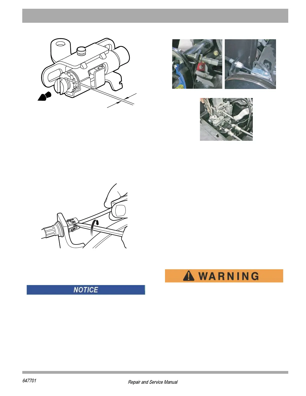
Figure 15 Setting Adjuster Screw
Brake Cable Snap Ring Removal
Rotate the ring to find the crease. Insert a flathead screw-
driver into the crease and twist screwdriver counterclock-
wise to pry ring apart and free brake cable.
Figure 16 Brake Cable Snap Assembly Removal and
Installation
Brake Cable and Equalizer Assembly
Removal and Installation
The brake cables and equalizer are only serviceable as
a complete assembly.
Remove the cotter pins and clevis pins to connect the
brake cables to the brake levers. Remove the retaining
rings connecting the brake cables to their brackets at the
axle (rear of cable) and at the frame (front of cable).
Loosen and remove the jam nut and the spherical nut on
the equalizer link (Figure 17). Inspect the hardware and
replace if needed. Remove the brake cable and equalizer
assembly and discard.
Figure 17 Brake Cable, Equalizer and Compensator
Slide the equalizer link of the new assembly over the
compensator rod. Loosely install the spherical nut and
new locking jam nut. Insert the cables into the frame and
axle brackets. Install new retaining rings. Connect the
cables to the brake levers using new clevis pins and new
cotter pins.
Adjust the brake pedal free travel. See ’Adjusting Brake
Pedal Free Travel’ on page 102.
Brake Pedal Assembly Replacement
Tool List................................................................... Qty.
Ratchet ........................................................................1
Torx Bit, T-45IP ............................................................1
Torque Wrench, in. lbs. ...............................................1
Wrench, 6mm ..............................................................1
Notched Pry Bar ..........................................................1
Insulated Wrench, 1/2".................................................1
Flat Blade Screw Driver ...............................................1
Using an insulated wrench, disconnect the bat-
tery cable at the negative (-) BL- battery
terminal.
To access the pedal assembly, remove the upper rocker
panels, the lower rocker panels and the floormat (refer
to page C2 for removal of rocker panels and floormat).
1. Remove four rivets (15) securing pedal cover (14) to
floorboard.
2. Remove pedal cover (14).
)\MWXMRK&VEOI7LSIW
%HNYWXMRsGPMGOWt1MRMQYQSJ
XLVIEHWQYWXFII\TSWIH
2I[&VEOI7LSIW
7GVI[EHNYWXMRKWGVI[MRYRXMP
XLVIEHWEVII\TSWIH
*VSRXSJ:ILMGPI
4EWWIRKIV7MHI
(VMZIV7MHI
%X&VEOI4IHEP