44
SPEED CONTROL
Read all of SAFETY and this section before attempting any procedure. Pay particular attention to Notices, Cautions, Warnings and Dangers.
Test drive the vehicle and confirm that the compression
spring adjustment results in the maximum governed
speed specified in the GENERAL SPECIFICATIONS sec-
tion.
Determine speed by measuring the time it takes to travel
a known set distance with vehicle at maximum speed.
Enter time and distance into this formula to calculate
speed:
• Rate (in MPH) = (Distance in feet / 5280) / (Time in
seconds / 3600)
• Rate (in KPH) = (Distance in meters / 1000) / (Time
in seconds / 3600).
For example:
• (300 ft. / 5280) / (13.6 sec. / 3600) = 15 MPH
• (100 m / 1000) / (15 sec. / 3600) = 24 KPH.
If the speed is not within the specified speed range, stop
the vehicle and adjust the governor compression spring
as described in procedure above.
Tightening the spring results in a speed increase, while
loosening it will result in a speed decrease.
Repeat the test and adjustment until the factory recom-
mended governed speed is achieved.
Install new safety seal on governor after calibrating the
vehicle.
Accelerator Pedal Assembly
Tool List Qty.
Ratchet ........................................................................ 1
Hex Bit, 5 mm .............................................................. 1
Torx Bit, T-20 ............................................................... 1
Torx Bit, T-30 ............................................................... 1
Torque Wrench, in. lbs. ............................................... 1
Torque Wrench, ft. lbs. ................................................ 1
Notched Pry Bar ..........................................................1
Insulated Wrench, 9/16” ..............................................1
Loctite
®
242.............................................................A/R
The accelerator pedal assembly is a modular unit. The
only serviceable items contained in the assembly are the
pedal pad and the throttle switch. The complete pedal
assembly may be replaced as a unit.
To access the pedal assembly, remove the upper rocker
panels, the lower rocker panels and the floormat. Remove
four ratchet rivets (1) securing the pedal cover (2) to the
floorboard and remove the cover from the pedal area.
cover (Figure 5).
Remove the brake kick-off linkage bolt (1) and disconnect
the accelerator cable (2) as described on the previous
page (Figure 7).
Remove three torx screws (3) and two self tapping screws
(6) (one each side of the pedal) securing the accelerator
pedal assembly to the floorboard and the two torx screws
(4) from the throttle switch (5). Remove the pedal assem-
bly (Figure 7).
Position the pedal assembly in the floorboard, aligning the
three mounting holes with the floorboard inserts. Install
three torx screws (3) but DO NOT tighten. Slide the pedal
assembly towards the front of the vehicle as far as it will
go.
Install the kick-off linkage bolt (1) and tighten the linkage
bolt (1) and the screw (3) to the torque value specified
below.
With the brake pedal in the full upright position, slide the
accelerator pedal towards the rear of the vehicle until
there is 1/8" (3.2 mm) gap (measured perpendicular to
the brake pedal arm) between the end of the kick-off link-
age rod (12) and the brake pedal arm.
Tighten the three torx screws (3). Install two self tapping
screws (7) in the two previously unused holes (in front of
and behind the pedal) in the accelerator pedal assembly
base and tighten the screws (7) to the torque value speci-
fied below.
Route wires for the accelerator pedal switch through the
floorboard channel. Plug the wire harness into the throttle
switch.
Install the pedal cover, floor mat and rocker panels.
Replace worn or damaged hardware as required.
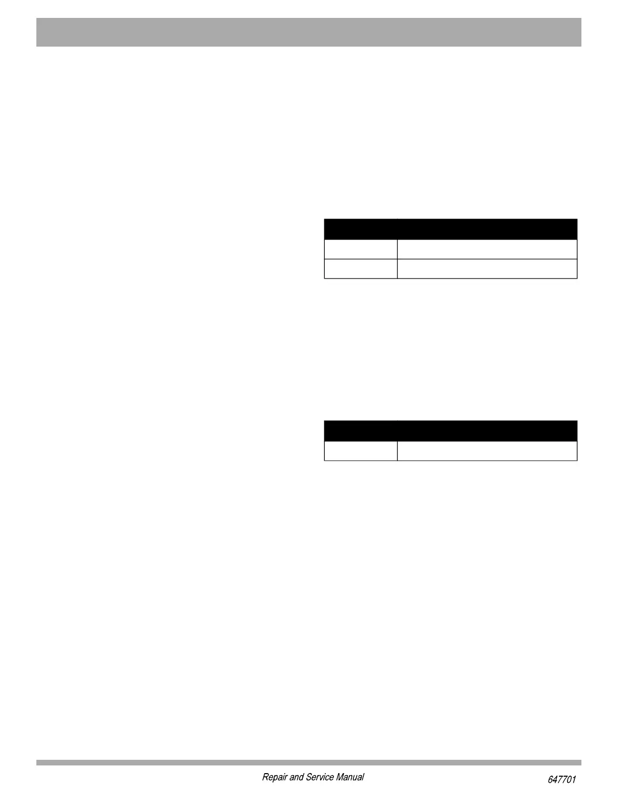
Item Torque Specification
1 15 - 17 ft. lbs (20 - 23 Nm)
3 17- 26 in. lbs (2 - 3 Nm)
Item Torque Specification
7 15 - 20 in. lbs (1.7 - 2.3 Nm)