SAFTEY
Read all of SAFETY and this section before attempting any procedure. Pay particular attention to Notices, Cautions, Warnings and Dangers.
11
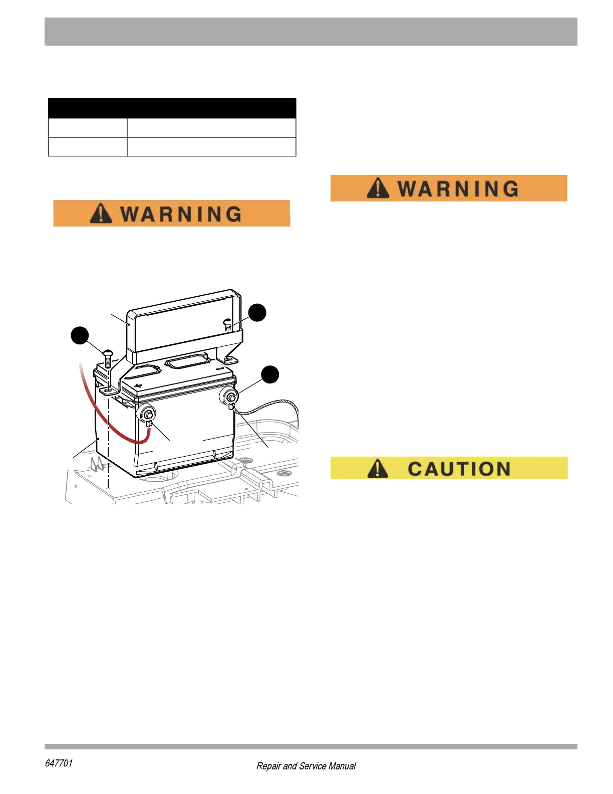
Tighten the bolt (1) and screw (2) to torque value speci-
fied below.
Be sure to remove all corrosion from the terminals and
hardware. After installing the battery, coat terminals with a
commercially available terminal protectant.
Be careful when you use aerosol containers
near battery terminals. Use a metal container
that has insulation to decrease the risk of an
explosion.
Figure. 1 Battery Removal
LIFTING THE VEHICLE
Tool List Qty.
Floor Jack ....................................................................1
Jack Stands .................................................................4
Wheel Chocks..............................................................4
You must lift the front, the rear or the entire vehicle for
some service and maintenance operations.
The vehicle is not stable during the lifting
process.
Make sure the vehicle is on a hard and level
surface.
Never get under a vehicle that is supported by
a jack only.
Make sure a vehicle that is supported on jack
stands is stable before you get under the
vehicle.
Put wheel chocks in front and behind the
wheels that remain on the ground.
Do not allow any person in or on the vehicle
being lifted.
Remove payload from vehicle before lifting. No person(s)
should be in or on the vehicle while lifting.
When you lift the vehicle, put the jack and jack
stand at the areas indicated only (Figure. 2).
How to lift the entire vehicle:
1. Install wheel chocks in front and behind each front
wheel.
2. Center the jack under the bagwell.
3. Put a block of wood between the jack and rear
bumper. Lift the vehicle enough to place two jack
stands under the frame where the leaf spring mount-
ing brackets are welded to the frame.
4. Lower the jack and test the stability of the vehicle on
the two jack stands.
5. Place the jack under the center front just behind the
bumper.
6. Lift the vehicle and place two jack stands under the
frame where the instrument panel support is
attached to the frame.
Item Torque Specification
1 70 - 90 in. lbs. (8 - 10 Nm)
2 27 - 44 in. lbs. (3 - 5 Nm)
&EXXIV]
&EXXIV]
&EXXIV]
&EXXIV]
8MI(S[R