20
Repair and Service Manual
BODY
Read all of SAFETY and this section before attempting any procedure. Pay particular attention to Notices, Cautions, Warnings and Dangers.
647701
10. Lift the rear body, pivot the seat opening upward and
towards the back of the vehicle to clear the seat back
supports.
Installation is reverse order of removal of removal.
Replace any worn or damaged hardware. It is recom-
mended that all lock nuts be replaced after the fifth
removal.
Tighten the screws (26, 30, 33, 34) to the torque value
specified below.
Rear Bumper
Tool List Qty.
Ratchet ........................................................................ 1
Ratchet Extension, 9" .................................................. 1
Universal Joint ............................................................. 1
Socket, 15mm..............................................................1
Torx Bit, T-47IP ............................................................ 1
Torque Wrench, ft. lbs.................................................. 1
The rear bumper (38) can be removed without removing
the rear body of the vehicle (Figure 10).
1. Remove two torx head screws (35) from the bag well
floor. If the rear body has been removed from the
vehicle go to step 2.
2. Remove four hex head bolts (37) securing the rear
bumper (28) to the vehicle frame.
3. Pull the rear bumper (28) backward off the frame
while lifting the rear edge of the body.
Installation is in the reverse order of removal. Replace
any worn or damaged hardware.
Tighten the screws (35), bolts (37) to the torque value
specified below.
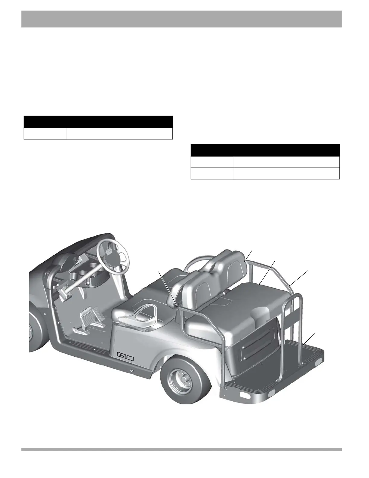
Figure 11 2 + 2 Rear Facing Seat and Foot Rest
Item Torque Specification
26, 30, 33, 34 13 - 16 ft. lbs. (18 - 22 Nm)
Item Torque Specification
35 6 - 9 ft. lbs. (8 - 12 Nm)
37 10 - 13 ft. lbs. (14 - 17 Nm)
7IEX&SXXSQ
7IEX&EGO
*SSX6IWX
,MT6IWXVEMRX
7IEX&EGO
7YTTSVX