36
FRONT SUSPENSION AND STEERING
Read all of SAFETY and this section before attempting any procedure. Pay particular attention to Notices, Cautions, Warnings and Dangers.
Steering Column Assembly and Yoke
Tool List Qty.
Wrench, 17 mm ...........................................................1
Ratchet ........................................................................ 1
Hex Bit, 8 mm .............................................................. 1
Torx Bit, T-45 IP ........................................................... 1
Torque Wrench, ft. lbs.................................................. 1
Remove the front bumper as shown in the BODY section.
Remove the front wheel(s) as described in the WHEELS
AND TIRES section.
1. Disconnect wiring for turn signals (if equipped) as
described in the ELECTRICAL section.
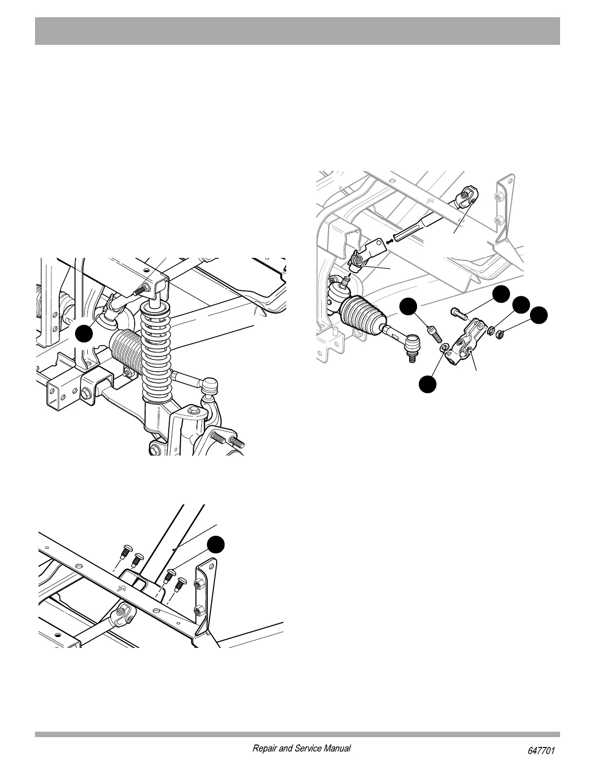
2. Remove the lower cross bolt (8) from the yoke (Fig-
ure 9).
Figure 9 Lower Cross Bolt
3. Remove four torx head screws (9) securing steering
column assembly to vehicle frame (Figure 10).
Figure 10 Steering Column Assembly Screws
4. Loosen the upper cross bolt (10) on the yoke. Slide
the yoke upward on the intermediate shaft to disen-
gage from the steering box pinion (Figure 11).
5. Turn the steering column assembly to the left 10° to
disengage the locking tabs. Lift the steering column
with intermediate shaft and yoke out of vehicle. Make
note of the location of the notch in the steering col-
umn mounting bracket (up or down).
6. To separate the yoke from the intermediate shaft,
remove the upper cross bolt (10), lock washer (12)
and nut (11). Pull the yoke off of the intermediate
shaft splines.
Figure 11 Upper Cross Bolt
7. Apply a commercially available anti seize compound
to the splines of the intermediate shaft and install the
yoke onto the shaft. Do not tighten the upper cross
bolt (10), washer (12) and nut (11).
8. To install the steering column assembly, align the
locking tabs on the mounting bracket with the slots in
the frame. Turn the assembly to the right 10° to align
the mounting holes. Make sure that the notch on the
steering column assembly mounting bracket is in the
same orientation as it was before removal (up or
down).
9. Install the four torx screws (9) finger tight and then
tighten to the toque specified.(Figure 10).
10. Apply a commercially available anti-seize compound
to the splines of the steering box pinion before
installing the yoke. Do not install the lower cross bolt
(8) at this time (Figure 9).
11. To align the steering wheel with the front wheels, use
the following procedure:
a. Install the front wheels if they were removed.
b. Remove the jack stands and lower the vehicle to
the ground.
c. Push the vehicle five feet backward and then five
feet forward.
7XIIVMRK
'SPYQR
=SOI
-RXIVQIHMEXI
7LEJX
=SOI