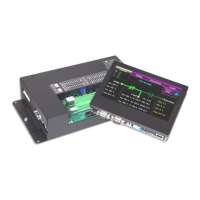
TSC 900 TRANSFER SWITCH CONTROLLER
PM 151 REV 5 16/04/19 Thomson Power Systems
Will not re-transfer to utility
source upon restoration (cont’d)
A Transfer Inhibit signal has been activated
Check TSC 900 indicators if a utility transfer inhibit
signal has been activated and reset)
On Service Entrance Rated ATS, Service
Disconnect switch is in the “De-Energized”
or “Transfer to Neutral” positions.
Switch to the Energized position
Electrical interlock contact from Gen
(Source 2) Switching Device (GSD) To
TSC 900 controller is not working correctly
• Check TSC 900 Digital Input DI-09 is correctly
mapped as “Source 2 Power switching device
Opened
• Check Digital input is correctly wired to Gen
(Source 2) Switching Device “b” auxiliary contact
• Check Gen (Source 2) Switching Device “b”
auxiliary contact is operating correctly (contact to
be closed when Switching Device is open)
Will not transfer to generator
source upon failure of utility
source
On Service Entrance Rated ATS, Utility
Voltage Disconnect switch inside ATS is
switched to “Off” position.
Switch Utility Voltage Disconnect switch to the “On”
position
Warm-up time delay function has not timed
out yet
Verify TSC 900 timer setting
Generator set output circuit breaker which
feeds ATS is open
Close generator set output circuit breaker
Generator supply is not operating at correct
voltage or frequency levels.
Verify correct nominal levels the generator should be
operating at and compare to TSC 900 Settings for
under/over voltage, voltage phase balance and
under/over frequency
TSC 900 has incorrect generator voltage or
frequency settings for the ATS.
Re-Program TSC 900 with correct settings as required
for voltage or frequency.
Generator Phase Rotation may not match
Utility supply (First Time Transfer).
Check Generator & Utility Voltage Phase rotation
matches on TSC 900 GHC Utility & Generator Voltage
Pages. If power cabling has non-matching phase
rotation, reverse power conductors on one phase on
one of the supplies
Electrical interlock contact from Utility
(Source 1) Switching Device (USD) To
TSC 900 controller is not working correctly
• Check TSC 900 Digital Input DI-08 is correctly
mapped as “Source 1 Power switching device
Opened
• Check Digital input is correctly wired to Utility
(Source 1) Switching Device “b” auxiliary contact
• Check Utility (Source 1) Switching Device “b”
auxiliary contact is operating correctly (contact to
be closed when Switching Device is open)
TSC 900 connection plugs are unplugged
(J1,2,3,4)
Verify all TSC 900 connectors are fully inserted
AC Voltage Sensing or Control Isolation
plugs (PL12 or PL15) are unplugged
Verify both PL12 & PL15 connectors are fully inserted
TSC 900 has “Transfer Fail” alarm
activated.
Determine cause of alarm and rectify before TSC 900
is reset on GHC
Defective ATS mechanism motor
Verify motor does not rotate when 120VAC is applied
directly to motor leads. If defective Return to Thomson
Power systems using RMA process
A loose control wire connection
Check all wiring connections in the ATS
Defective TSC 900 controller
• Verify TSC 900 has 120VAC control power
applied to the generator control power input (J1-
12, 13) and Diagnostic green LED is flashing.
• Verify TSC 900 has 120VAC control power
applied to the ATS control contacts (J1-1).
• Verify TSC 900 SCU has SD Memory Card fully
inserted into socket.
If defective Return to Thomson Power systems using
RMA process
Faulty motor limit switch
Verify Generator side limit switch (GLS) n/c contact is
closed and is low resistance when ATS mechanism is
not in the generator position.

 Loading...