TSC 900 TRANSFER SWITCH CONTROLLER
PM 151 REV 5 16/04/19 Thomson Power Systems
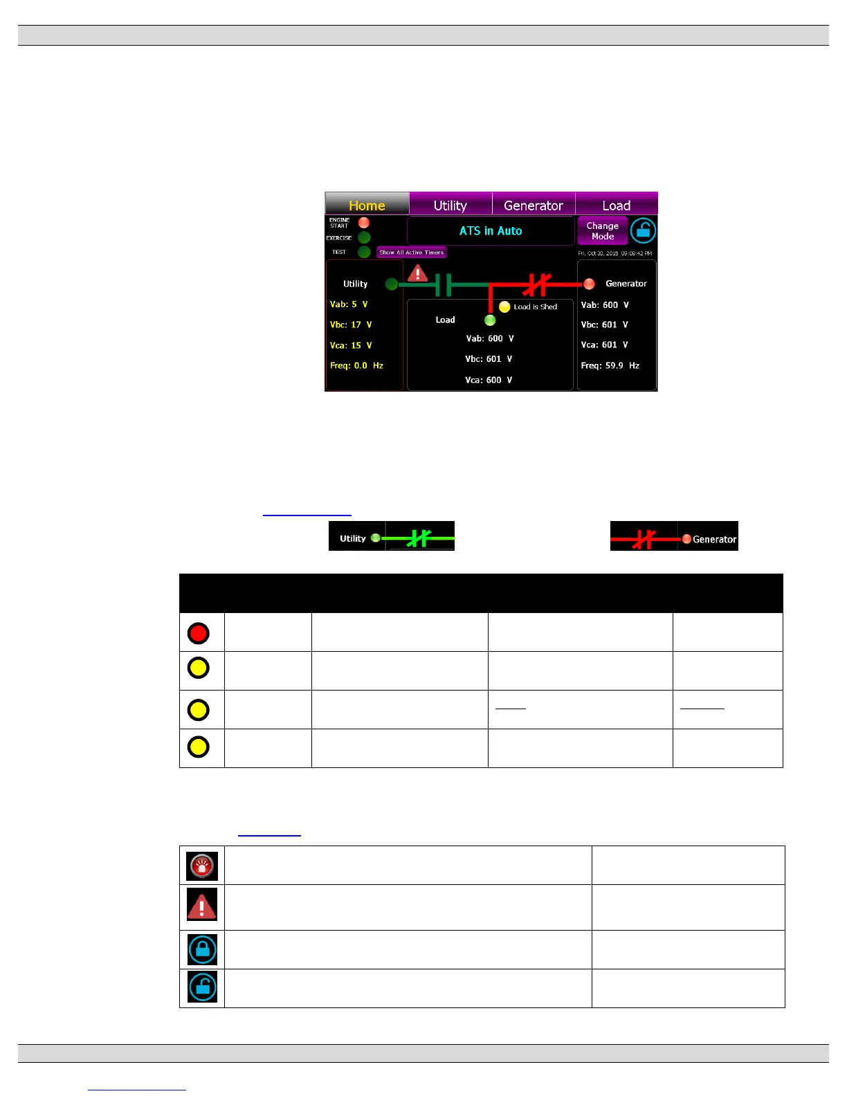
3.5.1. HOME PAGE
The Home Page is utilized as a summary control and monitoring screen for the ATS.
This screen provides a mimic bus showing current ATS position, identifies which sources
are energized, voltage levels and overall ATS operating mode. Phase to phase system
voltages will be displayed for each source and load.
The standard default mimic bus will automatically change color as follows:
• Utility –dark green = de-energized, light green = energized
• Generator - dark green = de-energized, red = energized
Note: Mimic Bus colors maybe customized to alternate colors.
Refer to Section 3.6.9 Power Switching Device status is depicted as follows:
• Utility Closed: Generator Closed:
The following Status LEDs are shown on the Home page:
Engine is not commanded to
start/run
Engine is commanded to
start/run
Exercise Schedule is not
enabled or active
Exercise Schedule is enabled
but not currently active
Exercise is
currently active
Local Test is active (On Load
or Off Load)
Test or Timed test modes can be activated from the Home page by press of the “Change
Mode” button which activates a pull down menu.
Refer to Section 5 of this manual for operating procedures.
Alarm Icon –flashes when a new Alarm has been activated
Press to view active alarms
Alert Icon -flashes when a source changes to an abnormal
condition
Press to view active voltage
source alerts
Security Icon - Settings Locked (Read only mode)
Press to access security login
Security Icon - Settings Un-Locked (Read/write mode)
Press to access security login