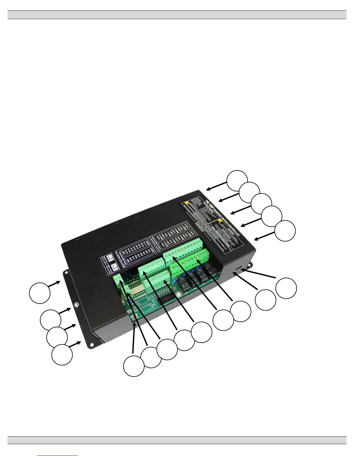
The Switch Control Unit (SCU) with case and main I/O connections are detailed in the following
diagram:
1. J9 – 24VDC Auxiliary Control Power
2. J2 – Utility Voltage Sensing (PH A, B, C, N)
3. J3 – Generator Voltage Sensing (PH A, B, C, N)
4. J4 – Load Voltage Sensing (PH A, B, C, N)
5. J5,6,7,8 – Load Current Sensing (PH A, B, C, N)
6. J21 –SCU SD Memory Card (Card Located inside case-not shown)
7. J11a Programmable Output Contacts #1-4
8. J11b Programmable Output Contacts #5-8
9. J12a Programmable Inputs #1-8
10. J12b Programmable Inputs #9-16
11. J10a Engine Start 2 Contact (Single Gen SRC 2)
12. J10b Engine Start 1 Contact (Dual Gen SRC 1)
13. J13 – GHC Aux 5VDC Power
14. J14- GHC USB Port
15. J15 – RS232 Programming Port
16. J1 – ATS Control
17. SCU Healthy Diagnostic LED
18. Engine Start Outputs On Diagnostic LED