System Five Setup
P/N 7010-0369 www.topconpositioning.com
1-5
System Five Setup
The System Five has several components that attach to each other
using cables. The cables allow communication between the Sensor,
the Control Box, and the Hydraulic Valves. When the Sensor
detects a change in slope or elevation, it sends a signal to the
Control Box, which then sends a pre-programmed, instructive
signal to the Hydraulic Valves. Once the valves receive the signal,
they raise or lower the implement according to the setup of the
Control Box.
After mounting the several System Five components to the
implement, use the following procedure to get started System Five.
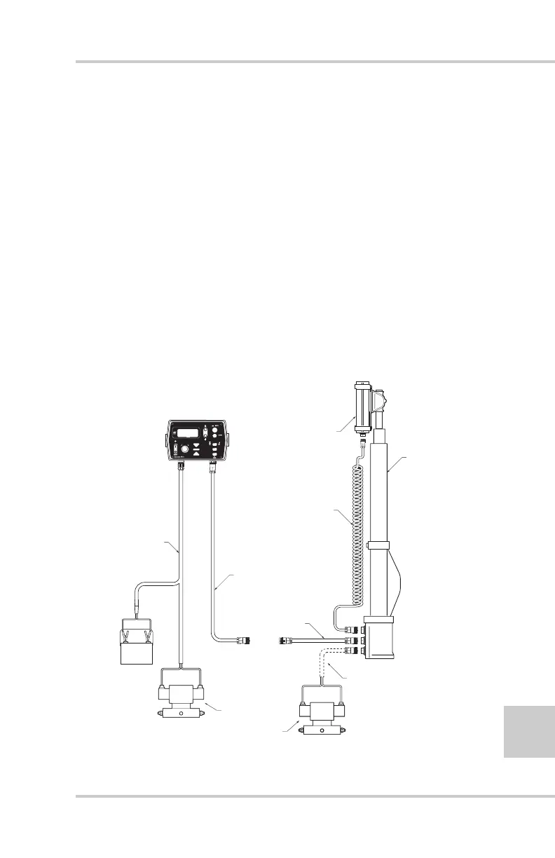
Figure 1-5 shows a generalized connection diagram for the tractor
and scraper components.
Figure 1-5. AG System Five Setup
POWER
+-
ower/Valve
Cable
Coil Cord
TM-1 Mas
TRACTOR COMPONENTS SCRAPER COMPONENTS
Hydraulic Valve
Connected To
Control Box
Or
Laser Mast
To Control Box
To TM-1 Mast
9256 Control Box
LS-B2 Laser
Receiver
Valve Cable
AUTO AUTO
Five
System
Five
System