Laser Axis Alignment
P/N 7010-0369 www.topconpositioning.com
3-9
5. Set the laser sensor to center the leveling bubble and get an
on-grade signal, and lock it into position (Figure 3-7).
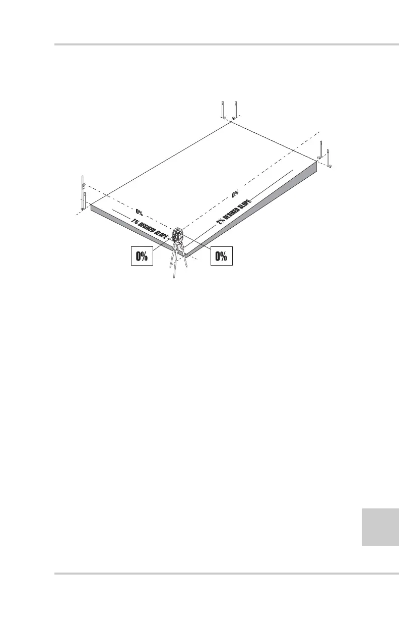
Figure 3-7. Laser and Grade Rod Positioning
6. Dial the slope into the laser transmitter on the axis facing
away from the detector. Leave the slope on the axis facing
the detector at 0%. If the laser is aligned properly, the grade
on the 0% axis will not change at the second hub, and the
detector will still have and on-grade signal (Figure 3-8 on
page 3-10).