TRANSPORTATION AND INSTALLATION MANUAL
143
13. Tool Interface (for the TS3100)
13.1. Tool wiring
The robot is provided with the tool cable air pipe and arm 1 (1) (arm 2 (2) and arm 3 as
options).
Connection to external equipment from the robot controller can also be made without
using the tool wiring in the robot arm.
Tool Signals (Controller Side) 13.1.1.
Eight input signals for components such as sensors, eight control signals for
components such as solenoid valves, 24 VDC, and 24 VDC GND are provided as tool
signals for the controller, thus enabling the wiring from the controller to external
equipment. (Cables between the controller and external equipment are optional.) The
signals are explained below.
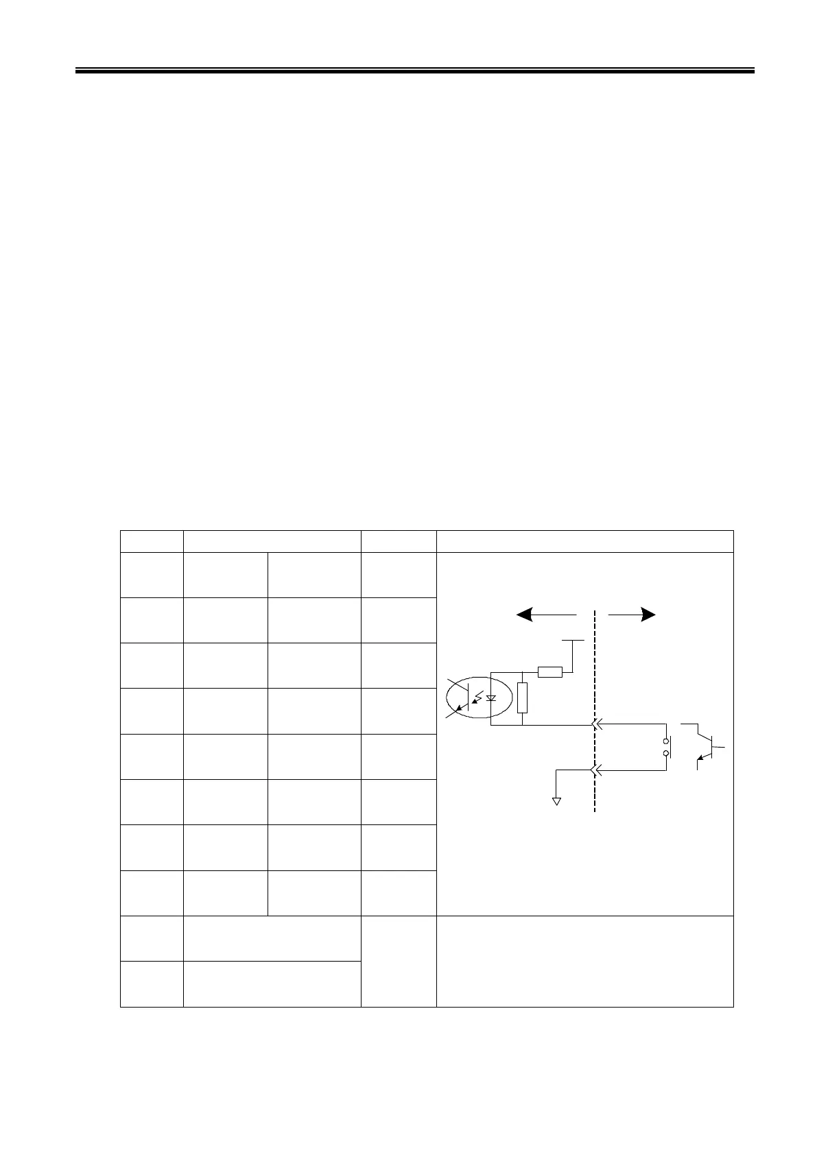
a-1) Input signal connector HAND (TS3100 Type-N)
Input circuit and example of connections
●
●
P24V
●
[Source type (+Common)]
TS3100
Customer’s side
P24G
Contact or
transistor
 Loading...