x
LIST OF FIGURES
Figure
Title Page
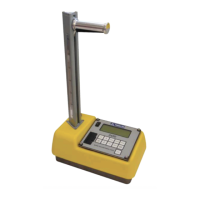
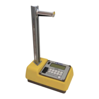
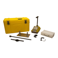
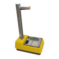
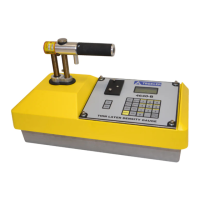
1–1 3440-L Gauge and Standard Accessories.............................. 1–5
1–2 3440-L Keypad Layout......................................................... 1–7
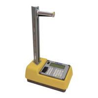
2–1 3440-L Gauge Showing Rod Positions............................... 2–14
2–2 Gauge Position on Reference Standard Block..................... 2–15
3–1 Drill Rod and Extraction Tool with Scraper Plate................. 3–2
3–2 Marking the Test Area .......................................................... 3–3
5–1 Gauge and Reference Standard Block Position
for Trench Offset................................................................. 5–11
5–2 Serial Port Location............................................................. 5–18
5–3 Sample Project Printouts..................................................... 5–20
5–4 Calculator Function Keys.................................................... 5–24
6–1 Stat Test Printout Sample...................................................... 6–6
6–2 Drift Test Printout Sample .................................................... 6–8
A–1 Direct Transmission Geometry ............................................ A–2
A–2 Backscatter Geometry.......................................................... A–3
A–3 Depth of Top Layer.............................................................. A–4
A–4 Effect of Moisture on Depth of Measurement...................... A–7
B–1 Diagram of an Atom..............................................................B–2
B–2 Variation of Radioactive Emission........................................B–4
C–1 Effect of Distance on Exposure.............................................C–3
C–2 3440-L Gauge and Transport Case........................................C–4
D–1 Sample Notice to Employees ............................................... D–6
 Loading...