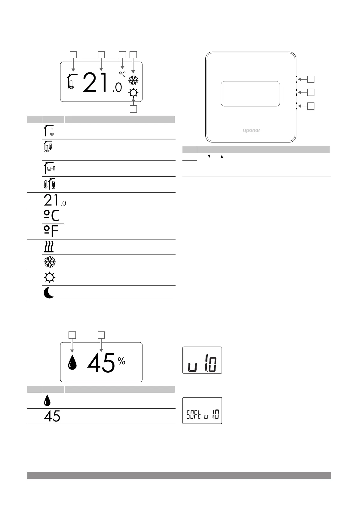
Control mode
The figure shows all possible symbols and characters that can be
shown on the display:
Item Icon Description
A Current control mode
Indoor temperature indicator
Current control mode
Indoor temperature with floor temperature limitation
indicator
Current control mode
Remote sensor temperature indicator
Current control mode
Outdoor temperature indicator
B Temperature unit, shown when the character group A
shows a temperature
C Temperature unit
D Heating demand
Cooling demand
E Comfort mode
ECO mode
Relative humidity
The figure shows all possible symbols and characters that can be
shown on the display:
Item Icon Description
A Relative humidity level
B Relative humidity reading using two digital characters.
Indicated with a “%” character
Button layout
The figure below shows buttons used to operate the digital
thermostats.
Item Description
A The and buttons are used to:
• Adjust setpoint temperature
• Modify settings menu parameters
B
C The OK button is used to:
• Toggle between current status data, and values of available
sensors connected to the thermostat
• Enter and exit the settings menu
• Confirm a setting
14.3
Start up
Analogue thermostats
The thermostat will perform a self test, for about 10 seconds, when
starting up. The system will be blocked for input and the thermostat
LED flashes during this period.
Digital thermostats
When starting up, the software version is shown in the display for
about three seconds. Then the thermostat enters run mode (except
the programmable thermostat which may require the time and date to
be set).
Software version
T-166
Current software version is displayed during power up.
T-168
Current software version is displayed during power up.
86
|
Uponor Smatrix Wave PULSE
|
Installation and operation manual
 Loading...