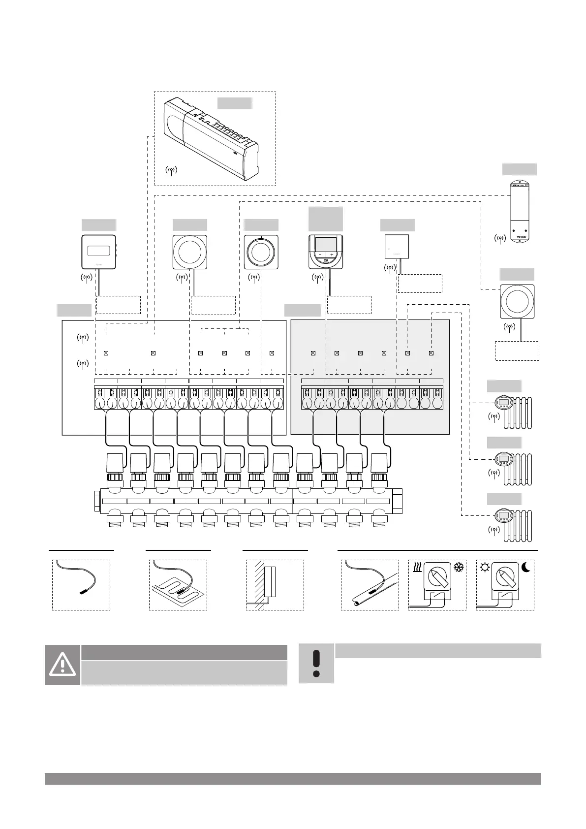
4.3 Installation example
03
#01 #08#03
02a 02b01b01a 09 10 11 12080704 05
030201 04 05
06
M-262*
M-161
T-163T-169
X-265
T-166
T-168
A+B+C
B
A+B+C
DA
T
S
TT T
#11
T-161
T
T
T
T
#06
T-165
T
S
A+B+C+D
#03
T-163
S
C+D
CB
S
X-265
SD0000011
24 V 24 V 24 V 24 V 24 V 24 V 24 V 24 V 24 V 24 V 24 V 24 V
T-162
T-162
T-162
*) This example contains optional accessories which adds six actuator outputs
(slave module M-160) to the Uponor Smatrix Wave PULSE room controller
Caution!
Only 24 V Uponor actuators are compatible with the
room controller.
See Wiring diagram, Page 115, for more information
Uponor Smatrix Wave PULSE system
Note
Setting up a system with a communication module
requires a mobile device (smart phone/tablet).
A connection example of Uponor Smatrix Wave PULSE room
controller (six channels) with an optional Uponor Smatrix Wave
PULSE Slave Module (six extra channels) using system devices (S)
and thermostats (T) as shown in figure.
The installation will work in a standard way with the thermostats
regulating each room according to their set temperatures.
Uponor Smatrix Wave PULSE
|
Installation and operation manual
|
17

 Loading...