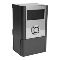
8. Exit registration mode
Press and hold the OK button on the room controller until the green
LEDs turn off to end registration and return to run mode.
9.5
Use relay module to connect
fan coils
Caution!
Uponor recommends connecting no more than 4 fancoils
per room controller to maintain the regulating
performance.
Caution!
In rooms with a fan coil, make sure that an actuator is not
connected to the first room channel, as that channel is
used to control the fan coil.
The relay module can be used to control fan coils in a room.
The fan coil is connected to a relay module which is registered to a
room thermostat channel, and is operated depending on settings in
the app (requires communication module). When selecting fan coil in
the cooling setting in the app, select the first room channel to where
the thermostat is registered.
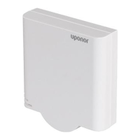
Connect fan coil to relay module
Warning!
Risk of electrical shock! Electrical installation and service
behind secured 230 V AC covers must be carried out
under the supervision of a qualified electrician.
Note
This connection requires dry contact sensing inputs in
the fan coil.
Note
This relay function requires a communication module,
and must be set in Installer settings during initial
configuration, or in the System settings menu.
The system can control one fan coil per thermostat channel. The fan
coil is started and set to a low speed when the relays are closed.
1. Ensure that the power is disconnected from both the relay
module and the ventilation unit.
2. Connect the fan coil speed cable to the connector 1A and 1B on
the relay module.
3. Connect the fan coil on/off cable to the connector 2A and 2B on
the relay module.
Register fan coil connected relay module to
thermostat
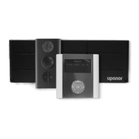
Connect power
Warning!
Risk of electrical shock! Electrical installation and service
behind secured 230 V AC covers must be carried out
under the supervision of a qualified electrician.
Connect the power cables from the relay module and cooling
components to a 230 V AC wall socket, or if required by local
regulations, to a junction box.
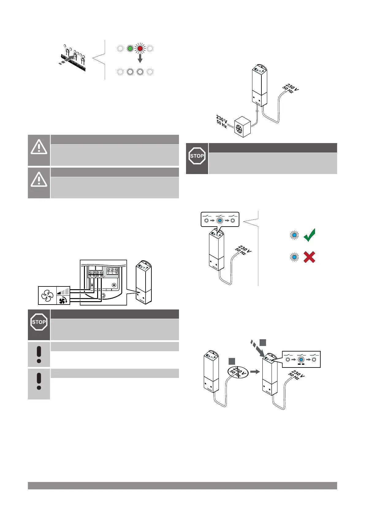
Power up the relay module
Power up the relay module and count the number of flashes of LED 2
(blue) to ensure it is in normal run mode.
LED 2: 1 flash = Normal (default)
LED 2: 2 flashes = Two stage additional cooling
Change relay module run mode
1. Power down the relay module and wait about 10 seconds.
2. Press and hold the button on the relay module while turning it on
again.
LED 2 flashes once (Normal run mode).
Uponor Smatrix Wave PULSE
|
Installation and operation manual
|
65
 Loading...