2AV/X
2-1-11
2-1
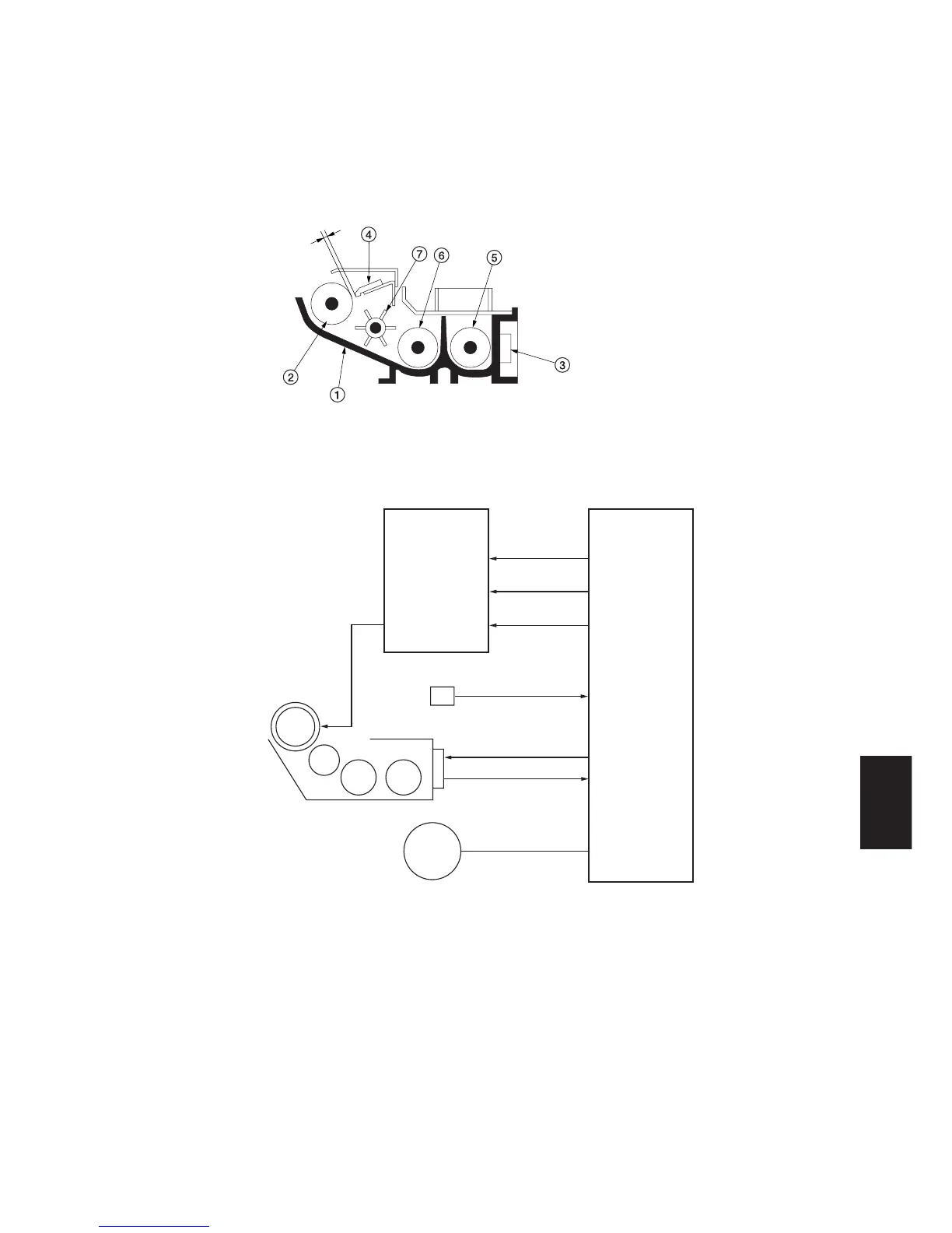
(1) Formation of magnetic brush
The developing roller consists of a magnet roller with five poles and a sleeve roller. Rotation of the sleeve roller around
the magnet roller entrains developer, which in turn forms a magnetic brush at pole N1 on the magnet roller. The height of
the magnetic brush is regulated by the doctor blade; the developing result is affected by the position of the poles on the
magnet roller and the position of the doctor blade.
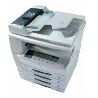
A developing bias voltage generated by the high-voltage transformer PCB (HVTPCB) is applied to the developing roller
to provide image contrast.
A
A: Distance between the doctor blade and developing roller: 0.6±0.05 mm
Figure 2-1-14 Forming a magnetic brush
CN4-1
24 V DC
MPCB
CN1-9
DB
HVTPCB
CN4-4
DB REM
CN1-6
CN4-7
CN13-2
CN13-3
CN11-1,2
DB CONT
TNS SIG
TNS CONT
CN1-4
CN13-7
WTDSW
TFM
Figure 2-1-15 Developing section block diagram
1 Developing unit housing
2 Developing roller
3 Toner sensor (TNS)
4 Doctor blade
5 Right developing spiral
6 Left developing spiral
7 Developing paddle