2AV/X
2-1-19
2-1
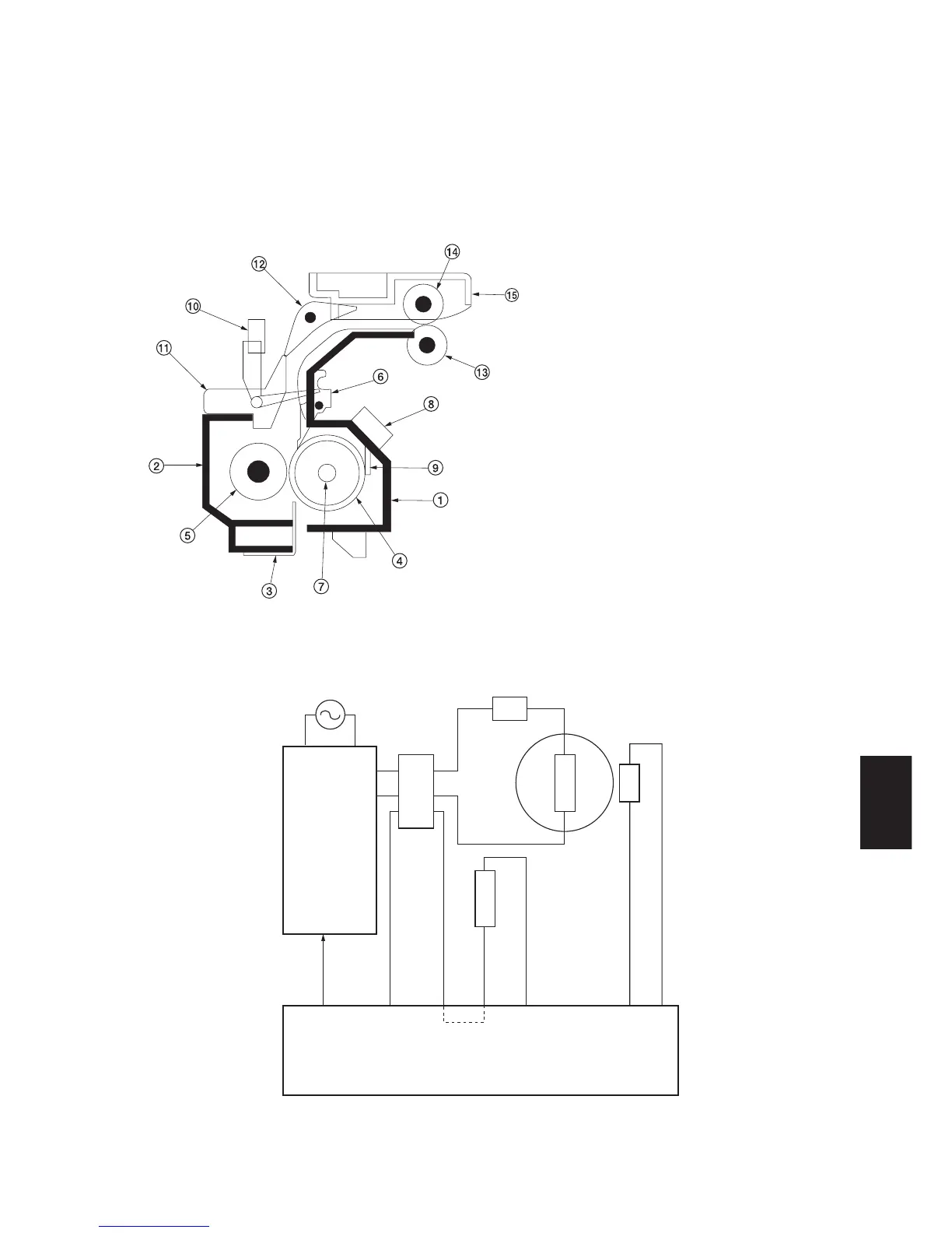
2-1-8 Fixing section
The fixing section consists of the parts shown in Figure 2-1-25. When paper reaches the fixing section after the transfer
process, it passes between the press roller and heat roller, which is heated by the fixing heater (FH). Pressure is applied
by the fixing unit pressure springs so that the toner on the paper is melted, fused and fixed onto the paper.
When the fixing process is completed, the paper is separated from the heat roller by heat roller separation claws and is
ejected from the fixing section by the rotation of the eject pulley and roller.
Figure 2-1-25 Fixing section
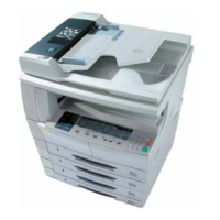
CN4-1CN3-3
FH REM
24 V DC
24 V DC R1
24 V DC R1
24 V DC R2
CN32-1
CN32-3
CN10-7
CN10-3
FTH
5 V DC
MPCB
PSPCB
CN2-1
CN2-3
CN12-9
CN12-8
FTS
Heat roller
FH
SSW1
FTH
SSW2
Figure 2-1-26 Fixing section block diagram
1 Upper fixing housing
2 Lower fixing housing
3 Fixing guide
4 Heat roller
5 Press roller
6 Heat roller separation claw
7 Fixing heater (FH)
8 Fixing unit thermostat (FTS)
9 Fixing unit thermistor (FTH)
0 Eject switch (ESW)
! Left fixing eject guide
@ Feedshift guide
# Eject roller
$ Eject pulley
% Eject guide