2AV/X
2-2-1
2-2
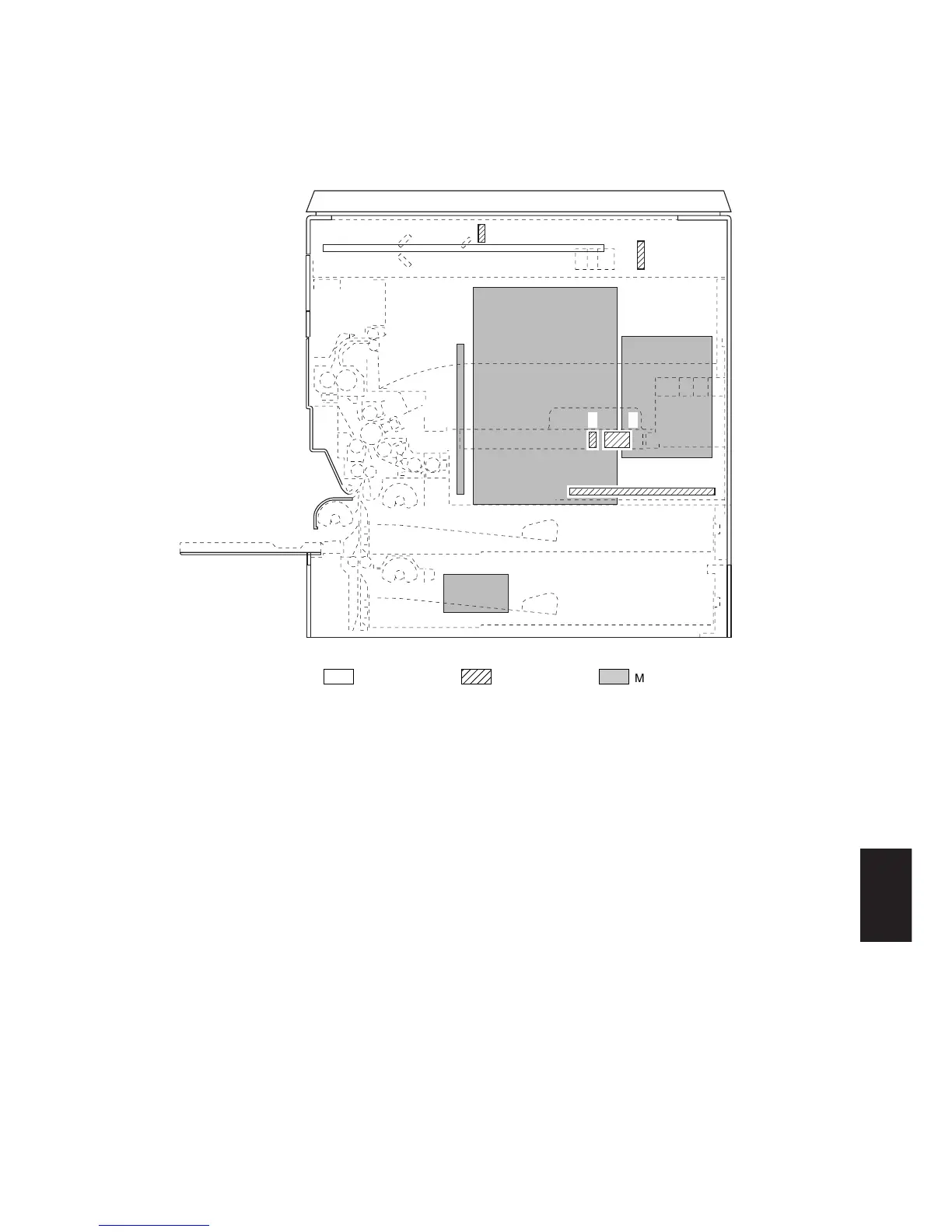
2-2-1 Electrical parts layout
(1) PCBs
Figure 2-2-1 PCBs
1. Main PCB (MPCB) ....................................... Controls the other PCBs, electrical components and optional devices.
2. Power source PCB (PSPCB) ....................... Generates 24 V DC, +12 V DC, 5V DC and 3.3 V DC; controls the fixing
heater.
3. High-voltage transformer PCB (HVTPCB) ... Main charging. Generates developing bias and high voltages for
transfer.
4. Inverter PCB (INPCB) .................................. Controls the exposure lamp.
5. CCD PCB (CCDPCB) .................................. Reads the image off originals.
6. Operation unit PCB (OPCB) ........................ Consists of the operation keys and display LEDs.
7. Laser diode PCB (LDPCB) .......................... Generates and controls the laser light.
8. Beam detection PCB (BDPCB) .................... Detects the laser light.
9. Memory PCB* (MEMPCB) ........................... Reads and outputs the image.
10. Drawer drive motor PCB* (DDMPCB) .......... Controls the drawer drive motor in the lower drawer.
*Optional for the 15 cpm copier/standard for the 20 cpm copier (the main PCB and memory PCB are integrated on one
PCB).
1
2
3
9
5
4
6
10
7
8
Machine front Machine inside