2AV/X
2-1-13
2-1
(4) Correcting the toner sensor control voltage
The toner sensor control voltage is corrected based on the absolute humidity and the total drive motor time so that the
toner density is kept constant regardless of the changes in humidity and the total drive motor time.
Toner sensor control voltage after correction = A + B + C
A: Toner sensor control voltage before correction (value set by maintenance item U131)
B: Correction data based on the absolute humidity
C: Correction data based on the total drive motor time
• Correction based on the absolute humidity
+15
Correction data
1.5 4.0 10.0 19.0
Absolute humidity (g/m
3
)
0
0
-15
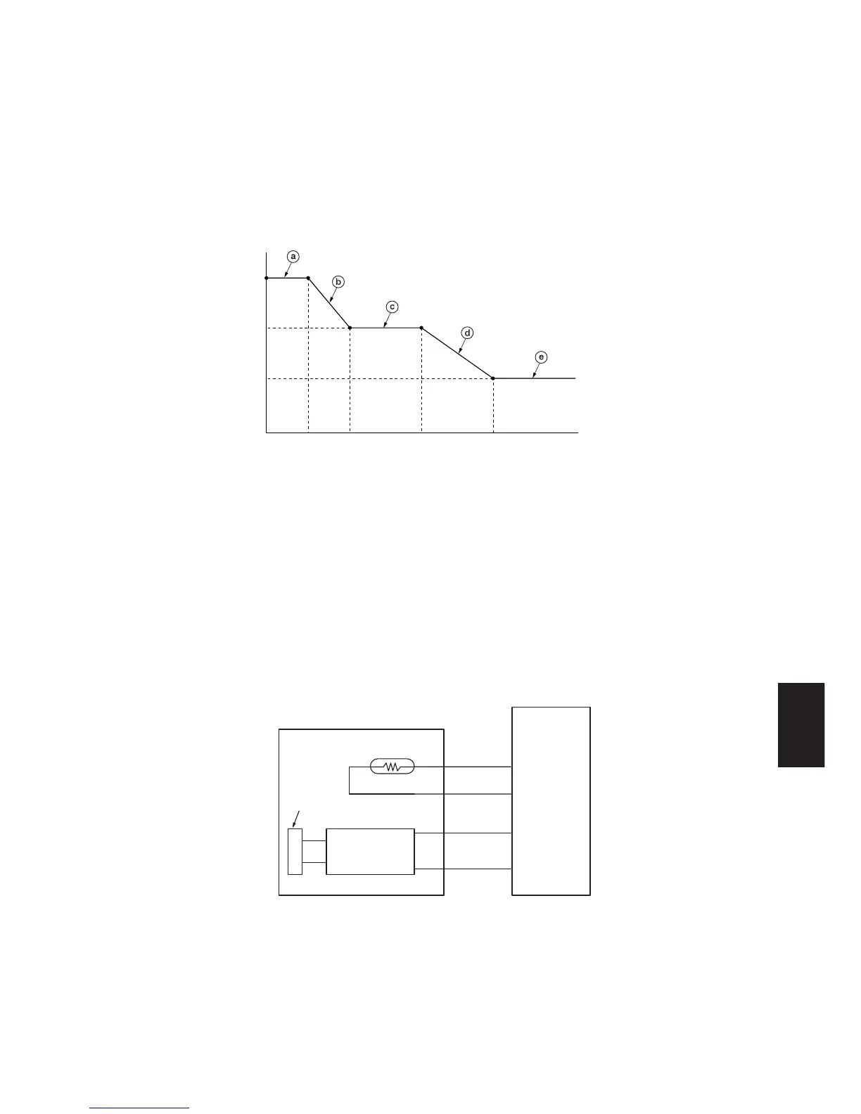
Figure 2-1-17 Correction based on the absolute humidity
a: When the absolute humidity is between 0 and 1.5 g/m
3
, a constant value of +15 is added to the toner sensor control
voltage.
b: When the absolute humidity is between 1.5 and 4.0 g/m
3
, the correction data is reduced according to the rise in
absolute humidity.
c: When the absolute humidity is between 4.0 and 10.0 g/m
3
, the correction data becomes 0.
d: When the absolute humidity is between 10.0 and 18.0 g/m
3
, the correction data is decreased according to the rise in
absolute humidity, reducing the toner sensor control voltage.
e: When the absolute humidity exceeds 18.0 g/m
3
, the correction data becomes a constant value of –15, decreasing the
toner sensor control voltage.
Computing the absolute humidity
The humidity sensor (HUMSENS) converts the relative humidity detected by the humidity sensing element into a voltage
and sends it to the main PCB (MPCB). The main PCB (MPCB) computes the absolute humidity based on this HUMSENS
signal and the temperature (ETTH signal) detected by the external temperature thermistor (ETTH).
MPCB
HUMSENS
2 HUMSENS
1 DC5V
CN7-1
CN7-2
CN7-3
CN7-4
4
3
ETTH
ETTH
GND
Humidity
sensing
element
Figure 2-1-18 Absolute humidity computation block diagram