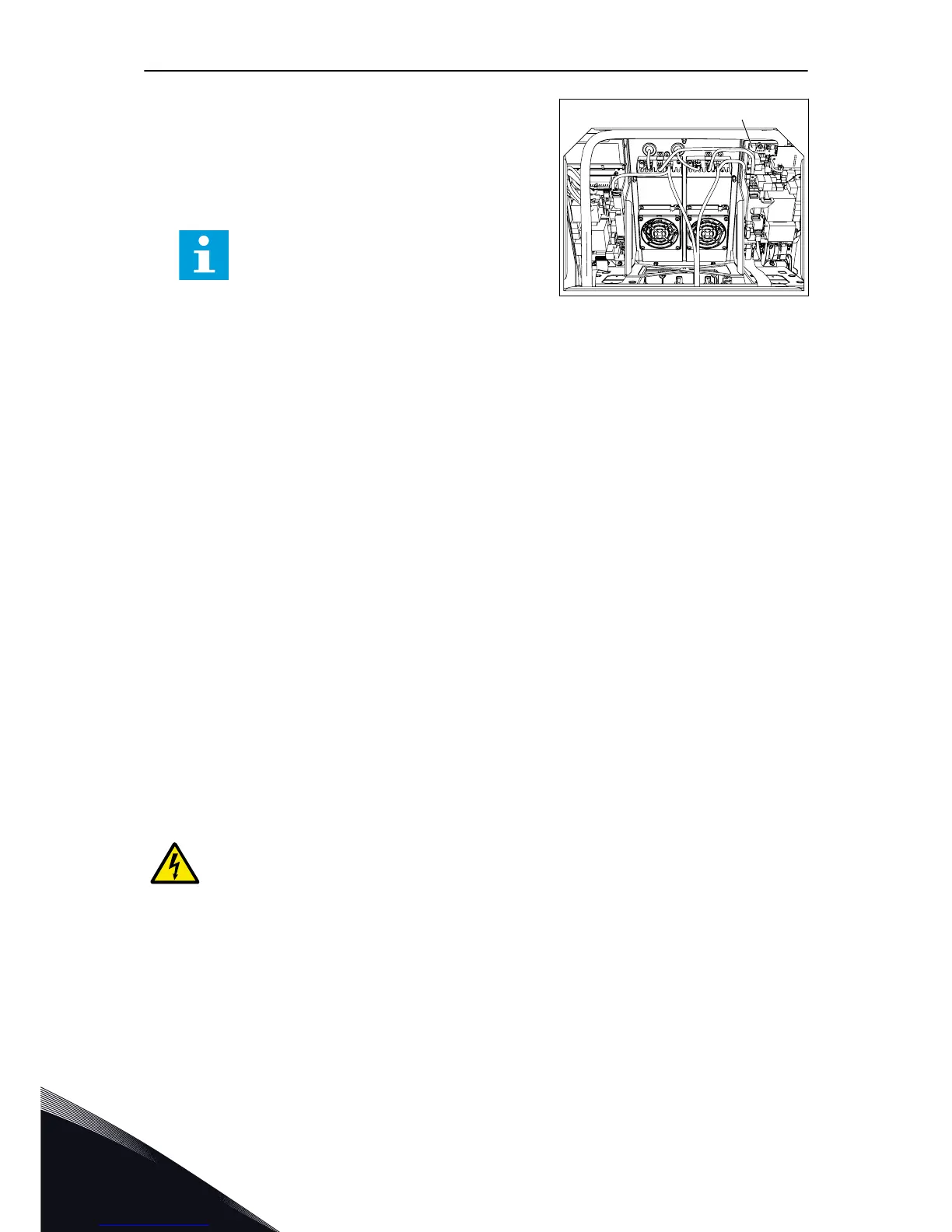
3 In MR10 and MR12, connect an external 24 VDC into
the connector X50 on the measurement board. The
connector pins are X50-22 (+) and X50-23 (-).
•
In MR12, connect the external 24 VDC to the
two X50 connectors.
NOTE!
The size of the power supply wire for the
external 24 VDC must be a minimum of 1
mm
2
. The lenght of the wire from the 24
VDC power supply to the X50 connectors
and to the control unit connectors must be
a maximum of 3 m (9.84 ft).
4 In all the enclosure sizes, do power-up to the
external 24 VDC power supply.
5 Remove the control panel. Connect the PC to the
control panel connector in the control unit with an
CAB-USB/RS485 cable.
6 Start the VACON
®
Loader PC tool.
7 Start the downloading of the software.
8 After the downloading is complete, disconnect the
PC and attach the control panel into the control
unit.
9 Do power-down to the external 24 VDC power
supply.
10 In MR8 and MR9, remove the external 24 VDC
power supply wires from the terminals. (Unless the
control unit of the drive is normally supplied with
an external 24 VDC supply.)
11 In MR10 and MR12, remove the external 24 VDC
wires from the X50 connector of the measurement
board. In MR12, there are two X50 connectors.
12 In MR10 and MR12, attach the service lid. In MR12,
there are two service lids.
13 After the downloading procedure is complete, start
the Startup wizard (see the Application Manual).
WARNING!
Before you connect the drive to mains, make sure that the front cover and the cable
cover of the drive are closed. The connections of the AC drive are live when the
drive is connected to mains.
VACON · 102 COMMISSIONING AND ADDITIONAL INSTRUCTIONS
8
LOCAL CONTACTS: HTTP://DRIVES.DANFOSS.COM/DANFOSS-DRIVES/LOCAL-CONTACTS/

 Loading...


