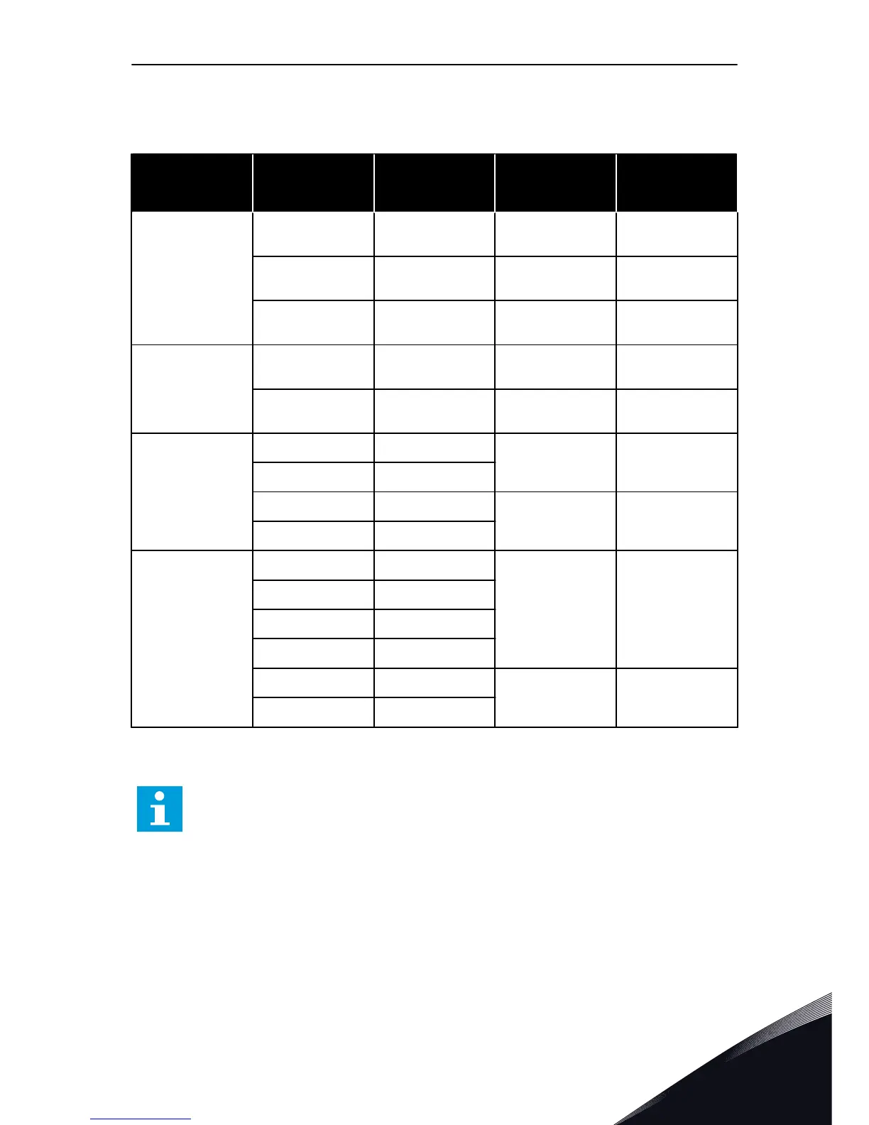
6.2 BRAKE RESISTOR CABLES
Table 21: Brake resistor cables, 208-240 V and 380-500 V
Enclosure size Type IL [A] Brake resistor
cable (Cu) [mm
2
]
Brake resistor
cable (Cu) [AWG/
kcmil]
MR8
0140 2
0140 5
140 3x70+35 4/0
0170 2
0170 5
170 3x95+50 300
0205 2
0205 5
205 3x120+70 350
MR9
0261 2
0261 5
261 2x(3x70+35) 2x3/0
0310 2
0310 5
310 2x(3x95+50) 2x4/0
MR10
0385 5 385
2x(3x95+50) 2x4/0
0460 5 460
0520 5 520
2x(3x120+70) 2x250
0590 5 590
MR12
0650 5 650
4x(3x95+50) 4x4/0
0730 5 730
0820 5 820
0920 5 920
1040 5 1040
4x(3x120+70) 4x250
1180 5 1180
One of the cable conductors stays unconnected. Use a symmetrically shielded cable, same
type as the mains and motor cables.
NOTE!
The different VACON
®
100 applications have different functions. For example, the
VACON
®
100 FLOW does not have the dynamic braking or the brake resistor
functions.
POWER CABLING VACON · 57
LOCAL CONTACTS: HTTP://DRIVES.DANFOSS.COM/DANFOSS-DRIVES/LOCAL-CONTACTS/
6
 Loading...


