Table 5: The options for MR8 and MR9
Option Order code Location Description
The brake chopper
+DBIN
The options module Enables dynamic braking with an exter-
nal brake resistor.
Flange mounting
+QFLG
- Enables mounting the drive through the
cabinet wall so that the control unit
stays inside the cabinet.
5.1.2 GENERAL INFORMATION ABOUT THE INSTALLATION, MR10
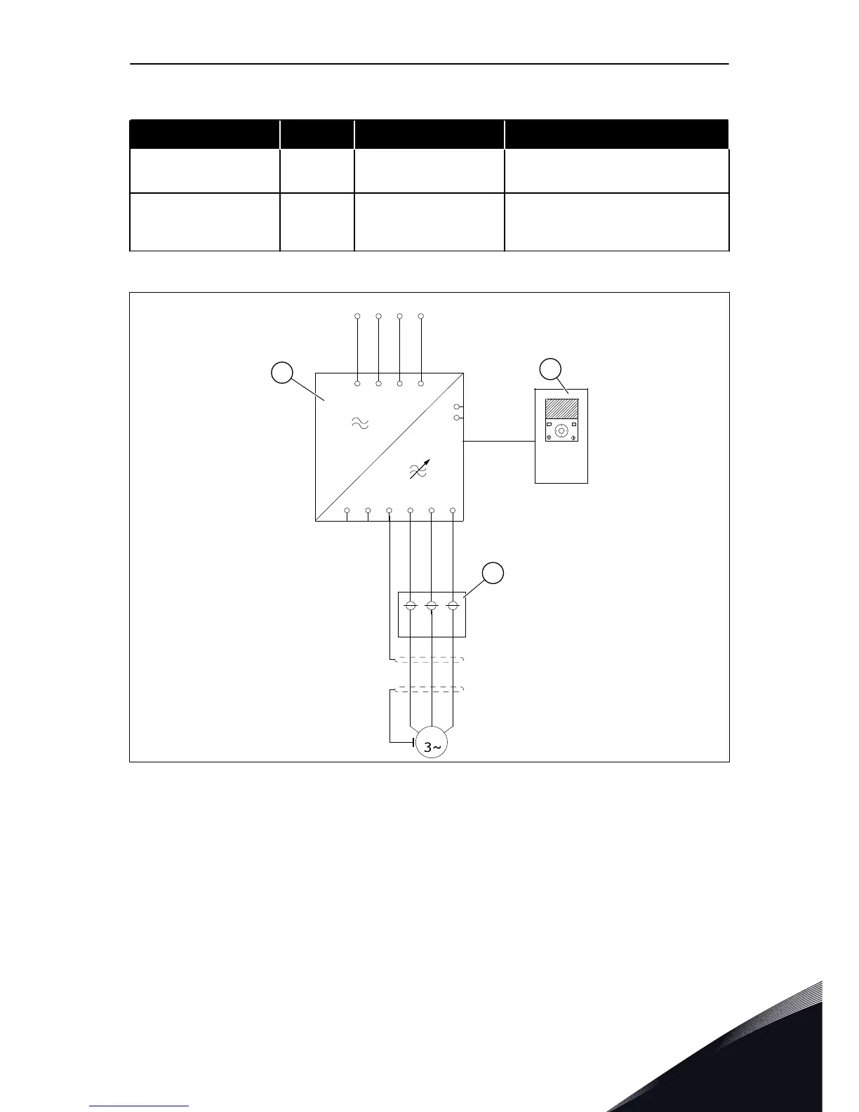
Fig. 13: The main circuit diagram, MR10 without the options module and options
A. The power unit
B. The control unit
C. The optional external power connection
block (+PCTB)
The optional external power connection block enables the connection of 3 motor cables to 1
terminal. It is also easier to connect large motor cables when you have this option.
The external power connection block is a loose option, install it near the IP00 drive module.
The cables between the motor cable terminals of the drive and the external power
connection block are not included in the delivery.
INSTALLATION INTO CABINET VACON · 31
LOCAL CONTACTS: HTTP://DRIVES.DANFOSS.COM/DANFOSS-DRIVES/LOCAL-CONTACTS/
5
 Loading...


