NOTE!
The different VACON
®
100 applications have different functions. For example, the
VACON
®
100 FLOW does not have the dynamic braking or the brake resistor
functions.
6.3 PREPARING FOR THE CABLE INSTALLATION
•
Before you start, make sure that none of the components of the AC drive is live. Read
carefully the warnings in chapter 2 Safety.
•
Make sure that the motor cables are sufficiently far from other cables.
•
The motor cables must cross other cables at an angle of 90°.
•
If it is possible, do not put the motor cables in long parallel lines with other cables.
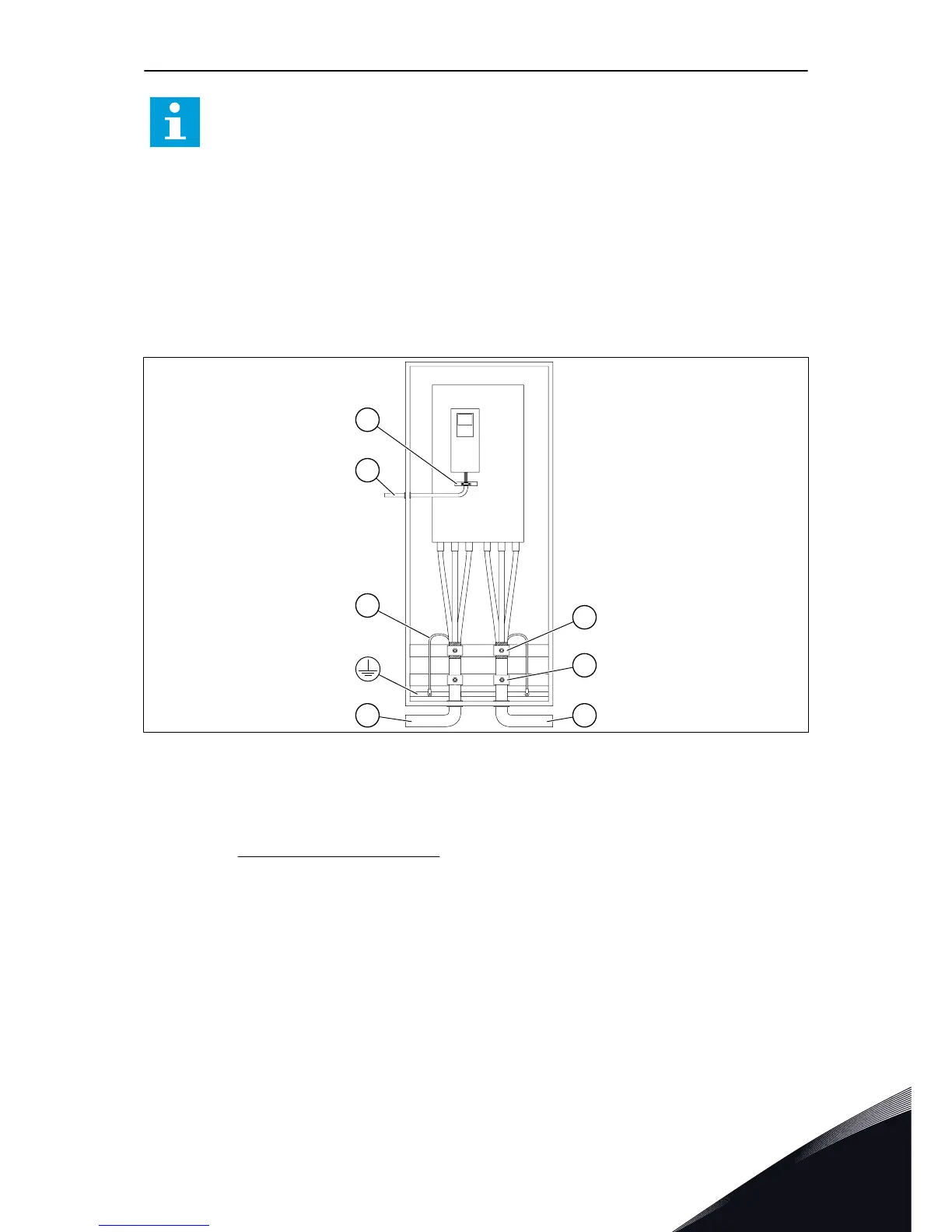
A. The mains cables
B. The motor cables
C. The grounding conductor
D. Pull relief
E. The grounding clamp for cable shield,
360° grounding
F. The control cable
G. The grounding bar of the control cable
•
Only use
symmetrically EMC shielded motor cables.
•
The maximum length of shielded motor cables is 200 m (MR8-MR12).
•
If the cable insulation checks are necessary, see chapter 8.3 for instructions.
•
If the motor cables are in long parallel lines with other cables, obey the minimum
distances.
•
The minimum distances are also valid between the motor cables and the signal cables of
other systems.
POWER CABLING VACON · 59
LOCAL CONTACTS: HTTP://DRIVES.DANFOSS.COM/DANFOSS-DRIVES/LOCAL-CONTACTS/
6

 Loading...


