Table 7: The options for MR12
Option Order code Location Description
The brake chopper
+DBIN
The options module Enables dynamic braking with an exter-
nal brake resistor.
The common mode filter +POCM The options module Decreases motor bearing currents.
The du/dt filter
+PODU
The options module Decreases motor bearing currents and
the stress on the motor insulation.
The external power con-
nection block
+PCTB
The cabinet Enables a more flexible connection of
motor cables. A loose option.
Installation kit for a
detached control unit ENC-QCDU
- An assembly plate and a 2 m cable to
install the control unit separated from
the power unit.
NOTE!
When your AC drive has the options module, more space is necessary for the
installation of the drive.
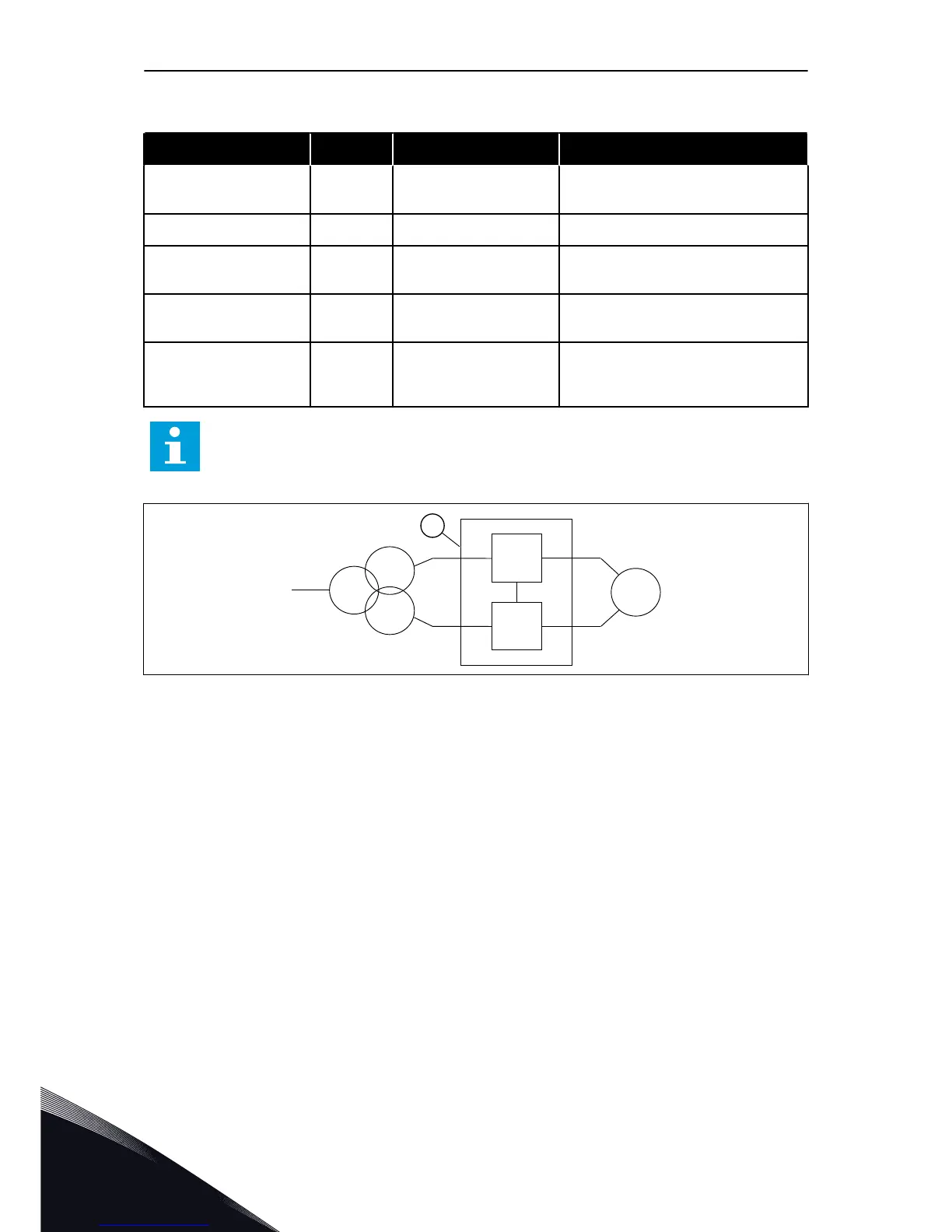
Fig. 17: The 12-pulse operation of MR12
A. The MR12 drive
With MR12 you can also use a 12-pulse connection to reduce the harmonics level in the
supply side of the drive. In the 12-pulse connection, the parallel drives are cabled to the
transformer's secondary windings that have a 30-degree phase shift.
5.2 MECHANICAL INSTALLATION
Install the AC drive in a vertical position at the rear plane of the cabinet. We recommend that
you attach rails on the sides inside the cabinet. The rails make the drive more stable and the
servicing easier.
Install the AC drive in the center of the cabinet width-wise and at a maximum distance of 230
mm from the top.
VACON · 36 INSTALLATION INTO CABINET
5
LOCAL CONTACTS: HTTP://DRIVES.DANFOSS.COM/DANFOSS-DRIVES/LOCAL-CONTACTS/

 Loading...


